Page 10 For technical questions, please call 1-888-866-5797. Item 57368
Setting and Testing
TO PREVENT SERIOUS INJURY FROM
ACCIDENTAL OPERATION: Make sure that the
Power Switch is in the off-position and unplug
the tool from its electrical outlet before
performing any procedure in this section.
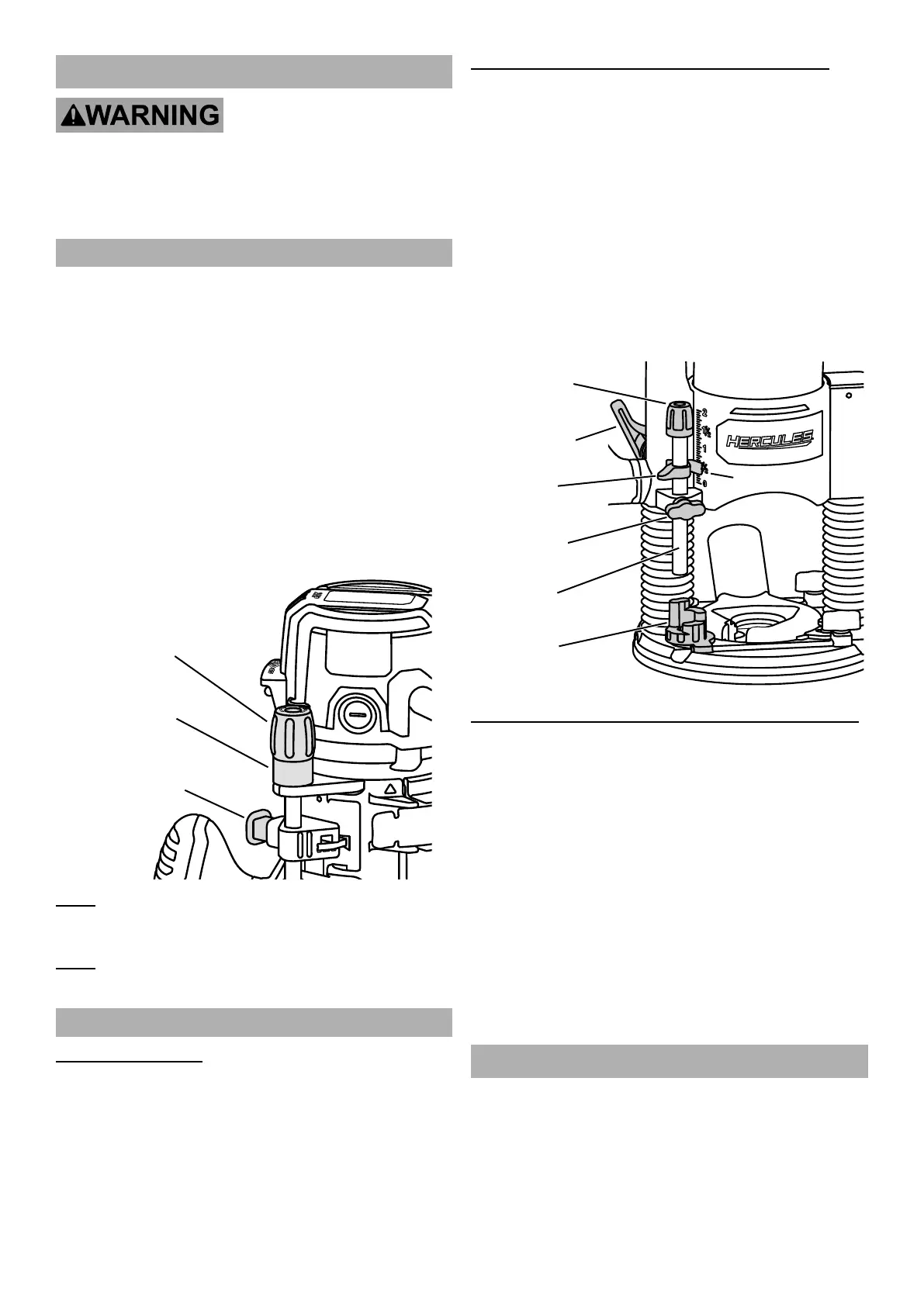
Depth Adjustment – Fixed Base
1. Install the Cutting Bit as previously described.
2. Press the Depth Adjustment Button and
raise or lower the Motor Housing to place the
cutting bit at an approximate depth setting.
3. For marginal depth adjustments, use the Micro-Fine
Depth Adjustment Knob to set the exact desired
depth of cut. The Depth Indicator Ring on the
Knob is marked in 1/256" (0.1 mm) increments.
a. For example, turning the Depth Adjustment
Knob counterclockwise 180º (1/2 turn) will
lower the cutting bit 1/32" (0.8 mm).
b. Turning the Depth Adjustment Knob
counterclockwise 360º (1 full turn) will
lower the cutting bit 1/16" (1.6 mm).
Depth
Adjustment
Button
Depth
Indicator
Ring
Micro-Fine
Depth Adjustment
Knob
Note: The Depth Indicator Ring can be reset to zero “0”
without moving the Micro-Fine Depth Adjustment Knob,
allowing adjustments to begin from any reference point.
Note: Make a test cut on a piece of scrap material
to ensure that the adjustment is correct.
Depth Adjustment – Plunge Base
Basic Depth Setting
1. Move the Plunge Depth Lock Lever
up to the unlocked position.
2. Grip both Plunge Base Handles and apply
downward pressure on the plunge action until
the cutting bit reaches the desired depth.
3. Move the Plunge Depth Lock Lever
down to the locked position.
Depth Setting with Depth Rod / Depth Stop Turret
1. With the cutting bit installed, lower the Motor Housing
until the tip of the bit contacts the work surface.
2. Rotate the Depth Stop Turret to the lowest setting.
3. Loosen the Depth Stop Lock Knob and
lower the Depth Stop Rod until it contacts
the lowest step of the Turret.
4. Slide the Depth Indicator to align the red line
with zero on the Depth Scale, indicating the
point where the bit contacts the work surface.
5. Slide the Depth Stop Rod up until the red Depth
Indicator line aligns with the desired depth on
the Depth Scale. Tighten the Depth Stop Lock
Knob to secure the Stop Rod in position.
Depth
Stop Turret
Depth
Stop Rod
Depth
Indicator
Depth Stop
Lock Knob
Micro Depth
Adjustment
Knob
Plunge Depth
Lock Lever
Depth Scale
Micro Adjustment with Depth Rod / Depth Stop Turret
1. For marginal depth adjustments, use the Micro
Depth Adjustment Knob. Each complete
rotation of the Knob adjusts the plunging depth
by approximately 1/32" (0.8 mm). An indicator
line is marked on the Depth Stop Rod under the
Adjustment Knob to set a reference point of “0”.
2. Before setting the Depth Stop Rod and Depth
Stop Turret when adjusting plunge depth,
turn the Micro Depth Adjustment Knob down
(clockwise) several revolutions from the top.
3. After setting the Depth Stop Rod and Depth Stop
Turret, turn the Adjustment Knob counterclockwise
to increase depth the desired amount. To
reduce the plunge depth, turn the Adjustment
Knob clockwise to the desired amount.
Workpiece Set Up
1. Secure loose workpieces using a vise or clamps
(not included) to prevent movement while working.
2. Make sure there are no metal objects in the wood
which might make contact with the cutting bit.
3. Refer to maximum plunge depth in the Specifications
Table on page 5 for limitations on workpiece size.

 Loading...