Page 8 For technical questions, please call 1-888-866-5797. Item 59436
Template Guide Installation
Note: Template guide (sold separately) is for use with a
template on the workpiece only. Remove the Template
Guide when using this product for any other application.
1. Turn Router upside down, then remove four screws
from Base Plate, then remove Base Plate.
2. Install template guide in Base’s opening with
its collar facing away from the Base.
3. Replace Base Plate and secure with four screws.
4. Secure template (not included) to workpiece:
a. Determine template offset by subtracting bit
diameter from Template Guide outside diameter
and divide by two.
Example: Template Guide outside diameter
is 5/8″, minus the bit diameter of 3/8″ equals
1/4″, divide by two equals 1/8″ offset.
b. Secure template to workpiece using
appropriate offset from desired cut line.
Note: If clamps are used to secure
workpiece, make sure they do not
interfere with Router while cutting.
5. Place Router on template with collar of
template guide against edge of template. Apply
light pressure to keep template guide flat against
template edge. Cut material along desired cut line.
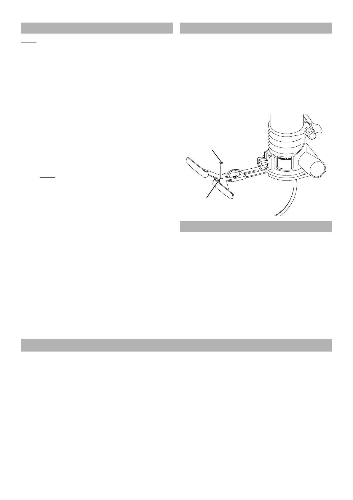
Circle Cutting
Use center hole in Fence as a pivot
point when cutting circles.
1. Install Fence according to Set Up Temporary Guide.
2. Loosen Fence Knob, set distance from center hole
in Fence to far edge of bit, equal to radius of circle.
3. Tighten Fence Knob.
4. Align center hole in Fence with center point of circle.
5. Drive a nail through center hole
to secure Fence in place.
Nail
Center
Hole
Adjusting Cutting Depth
1. Open Lock Lever, then turn Depth Adjustment Knob
until bit is retracted within Base.
2. Place Base on a flat surface, then slide
Motor down in Base until tip of bit contacts
workpiece. Close Lock Lever.
3. The Depth Scale indicates starting position.
Starting position will vary depending on bit used.
4. Add desired depth of cut to starting position.
Example: If starting position is 1/2″ and desired depth
of cut is 1/4″, correct adjustment on the scale is 3/4″.
5. Open Lock Lever, then use Depth Adjustment Knob
to move Motor up until scale shows correct
reading; in this example 3/4″. Close Lock Lever.
Workpiece and Work Area Set Up
1. Designate a work area that is clean and well lit.
The work area must not allow access by children
or pets to prevent distraction and injury.
2. There must not be objects, such as utility lines,
nearby that will present a hazard while working.
3. Route the power cord along a safe route to reach
the work area without creating a tripping hazard or
exposing the power cord to possible damage. The
power cord must reach the work area with enough
extra length to allow free movement while working.
4. Secure loose workpieces using a vise or clamps
(not included) to prevent movement while working.
5. Make sure there are no metal objects in the
wood which might make contact with the bit.
6. Refer to maximum cutting depth in the
Specifications Table on page 5.