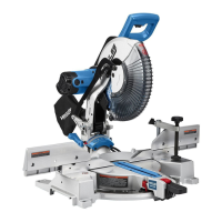
The HERCULES HE74 12" Double-Bevel Sliding Compound Miter Saw is a power tool designed for precise cutting of various materials, primarily wood. It allows for miter cuts (angles across the horizontal surface) and bevel cuts (angles vertically), as well as compound angles which combine both. The sliding feature extends its cutting capacity for wider workpieces.
Function Description:
The miter saw is used for making accurate crosscuts, miter cuts, bevel cuts, and compound cuts in wood and similar materials. It features a rotating turntable for miter angle adjustments and a tilting saw head for bevel angle adjustments. The sliding mechanism allows the blade to move across the workpiece, increasing the effective cutting width. A depth stop feature enables kerfing or rabbet cuts that do not cut entirely through the material. The tool is equipped with a Precision Blade Guide System (likely a laser or LED shadow line) to assist in aligning cuts. Safety features include blade guards, a head lock-down pin for transport, and a spindle lock for blade changes. Dust collection is facilitated by a dust outlet and a collection bag to maintain a cleaner work environment.
Important Technical Specifications:
- Electrical Rating: 120VAC/60Hz/15A
- Spindle No Load Speed: 4,100 RPM
- Max. Accessory Diameter: 12" Blade Diameter
- Arbor: 1" Round
- Capacity of Cut:
- Miter Angle: 50° Miter Left / 60° Miter Right
- Bevel Angle: 49° Bevel Left and Right
- Cutting Capacities (Height x Width):
- 0° Miter: 4-1/2" x 12-1/2" (Height), 3-1/2" x 14" (Width)
- 45° Miter: 4-1/2" x 8-1/4" (Height), 3-5/16" x 9-3/4" (Width)
- 45° Bevel Left: 2-7/8" x 9-7/8" (Height), 1-3/4" x 14" (Width)
- 45° Bevel Right: 1-15/16" x 12-1/8" (Height), 1-5/16" x 14" (Width)
Usage Features:
- Grounding: Double insulated with a polarized plug for electrical safety.
- Work Area Setup: Requires a clean, well-lit work area with sufficient space for extended workpieces. Workpiece support (saw table, stand) must be level with the saw table to ensure accurate cuts.
- Workpiece Securing: Workpieces should be secured with clamps to prevent kickback and improve cutting accuracy.
- Miter Angle Adjustment:
- Loosen the Miter Lock Knob.
- Pull up the Miter Detent Lever to unlock the turntable.
- Move the table to the desired angle, indicated by the Miter Angle Indicator.
- Pre-set detents are available at common angles (15°, 22.5°, 30°, 45° left and right).
- Micro-adjustments can be made by pulling up the Miter Detent Lever and pushing the Detent Latch Button forward to latch it in place, allowing free movement along the miter scale.
- Tighten the Miter Lock Knob after adjustment.
- Bevel Angle Adjustment:
- Loosen the Bevel Lock Knob at the rear of the saw.
- For micro-adjustments, push the Bevel Detent Lever back until it snaps into place and move the Saw Head Assembly to the desired angle, reading the angle on the Bevel Angle Indicator.
- For pre-set detents (22.5°, 33.9°, 45° left and right), push the Bevel Detent Lever back, move the Saw Head Assembly, then release the lever to lock into place.
- Lock the Saw Head Assembly by rotating the Bevel Lock Knob clockwise.
- A sample cut on scrap material is recommended to confirm accuracy.
- Important Safety Note: After any cutting angle adjustment, both sides of the fence must be adjusted clear of the blade's cutting path.
- Depth Stop:
- Used for kerfing or rabbet cuts that don't go through the workpiece.
- Pull out the Head Lock-Down Pin and raise the Saw Head.
- Rotate the Depth Stop down to a horizontal position.
- Adjust depth by loosening the Wing Nut on the Depth Adjustment Bolt, turning the bolt, and then re-tightening the Wing Nut.
- To disengage, rotate the Depth Stop up to its vertical position.
- Sliding Feature:
- For wide materials, loosen the Slide Lock Knob and pull the Saw Head Assembly forward.
- Press down on the Saw Handle and push the Saw Head toward the rear to make the cut.
- Light downward and lateral pressure should be used; avoid forcing the material.
- Blade Guide System: The Precision Blade Guide System (laser or LED shadow) can be turned ON to project the blade's shadow onto the workpiece for accurate alignment.
- Safety Precautions:
- Always wear eye protection and a face/dust mask if dusty.
- Keep hands out of the line of the saw blade.
- Do not operate without guards in place.
- Never reach around the saw blade.
- Disconnect power before changing blades or servicing.
- Wait for the blade to stop completely before moving workpiece or changing settings.
- Do not use damaged equipment; correct abnormal noise or vibration before further use.
- Ensure the Lower Blade Guard operates smoothly and properly protects the blade.
- Do not depress the spindle lock during operation.
- Use only blades rated to at least the maximum speed of the tool.
- Do not use high-speed steel, abrasive, metal-cutting, or masonry-cutting blades.
- Do not cut logs, tree limbs, or uneven lumber.
- When cutting wet, green, or pressure-treated lumber, use appropriate blades and wear a NIOSH-approved respirator with proper ventilation.
Maintenance Features:
- Pre-Use Inspection: Before each use, inspect for loose hardware, misalignment or binding of moving parts, cracked/broken parts, damaged electrical wiring, and any other condition affecting safe operation.
- Post-Use Cleaning: Wipe external surfaces with a clean cloth.
- Blade Replacement:
- Unplug the tool.
- Pull out the Head Lock-Down Pin, raise the Saw Head, and raise/hold the Lower Blade Guard.
- Loosen the Guard Plate Bolt and swing the Guard Plate up.
- Press and hold the Spindle Lock.
- Remove the Arbor Bolt (left-handed thread, turns CLOCKWISE to loosen) and Outer Flange.
- Install the new blade, ensuring the rotation arrow matches the Lower Blade Guard.
- Replace the Outer Flange and Arbor Bolt, positioning the cupped side of the flange against the blade.
- Hold the Spindle Lock and wrench tighten the Arbor Bolt (turns COUNTERCLOCKWISE to tighten).
- Release Spindle Lock, rotate Guard Plate back, and secure with the Guard Plate Bolt.
- Miter Scale Calibration:
- Unplug the tool.
- Lower and lock the Saw Head with the Head Lock-Down Pin.
- Loosen the Miter Lock Knob and move the table to 0° miter position, then release the Miter Detent Lever.
- Place a carpenter's square on the table, with one edge along the blade and the other along the fence, ensuring contact with the blade surface (not teeth).
- If the fence is not perpendicular, loosen the four screws holding the Miter Scale.
- Move the table and scale together until the blade and fence are perpendicular, then tighten the screws.
- Adjust the Miter Angle Indicator to zero if necessary by loosening its screw, moving it, and re-tightening.
- Bevel Angle Calibration: If adjustment is needed for the blade to be exactly vertical to the table, it must be serviced by a qualified technician.
- Kerf Board Adjustment/Replacement:
- If damaged, remove the six screws holding the old Kerf Board and install a new one, tightening screws slightly.
- To adjust, lower and lock the Saw Head.
- Adjust the Kerf Board so the right side of the blade slightly clears its edge.
- Loosen the Bevel Lock and set the Bevel Angle at 45° left.
- Ensure the left side of the blade clears the Kerf Board.
- Tighten the six screws holding the Kerf Board.
- Troubleshooting: A dedicated section provides common problems, possible causes (e.g., no power, worn brushes, dirty blade, material issues), and likely solutions. Always disconnect power before diagnosing or servicing.
- Qualified Technician: Procedures not specifically explained in the manual, or issues like a damaged power cord or bevel angle calibration, must be performed by a qualified service technician.