12
INSTALLING AN AIRHANDLER INTO AN EXISTING CUPBOARD,
THE FRONT PANEL OF WHICH IS NOT EASILY REMOVED
This is often the case with retrofits.
Please note: The installation requires that there be a minimum of 16mm between the
front of the A/H and the back of the front panel, to allow sufficient room for the
turning vanes on the facia to be accommodated.
If there is a 3 to 5 mm front panel, then a frame 16mm thick will need to be installed.
The cupboard door is removed, and the cutting template applied to the cupboard
front.
Firstly, however, refer to fig. 13 which shows a modified template. Draw the “New
Cutting Line” as described in fig. 13 onto the full sized template.
This hole will now measure 240 mm high, and include the control box cutout.
Apply the marked up template to the cupboard front, adjust for symmetry etc. tape
down, and drill the witness or pilot holes at the corners. Proceed then to cut out.
An adaptor frame is now constructed. See fig. 14.
The cutting template can be layed over this frame, the right end line “outside of
airhandler cabinet” is layed flush with the end of the frame. The same line is 10 mm
inside the top and bottom cutout. Mark and drill the 4x5 mm dia. holes used to pick
up the prepunched holes on the front of the A/H.
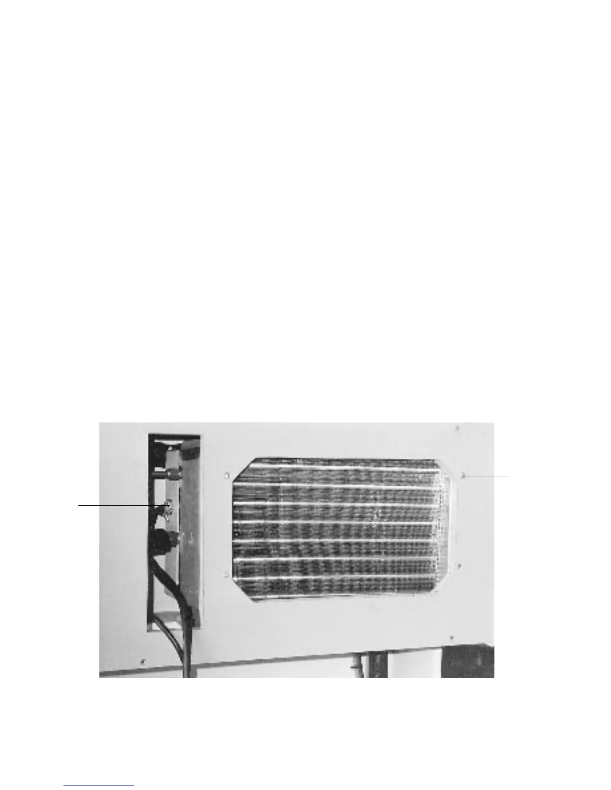
Figure 12
1 “P” SADDLE FOR THERMOSTAT BULB
2 CLAMPING SCREWS 4 OFF - COUNTER SINK.
THESE SCREWS PICK UP PREPUNCHED HOLES IN THE FRONT OF A/H.
MAX LENGTH SCREWS No.6 X 32M.
2
1