13
Now screw the frame to the A/H, using the 32 x no 6 screws provided (ensure they
are countersunk flush with the surface of the frame). See fig. 12 & 13.
Cut out the holes for the two return air grilles and install them. Now fit the two
support rails. The support rail height is best measured by initially inserting the A/H
(complete with timber sub frame fitted), and measure from underneath through a
return air frame. This way will give the correct height you need to make the two
rails. See fig. 10 & 15.
Install the drain as described in pp. 8 & 9.
Now run the pipework as pp. 4 & 8.
The A/H assy. can now be fitted with the subframe being screwed to the front
panel of the cupboard. See fig. 15.
Note: If the front panel is just 3 to 10 mm plywood, then extra framing will need
to be installed, so that the sub frame attached to the A/H can be screwed back to
it.
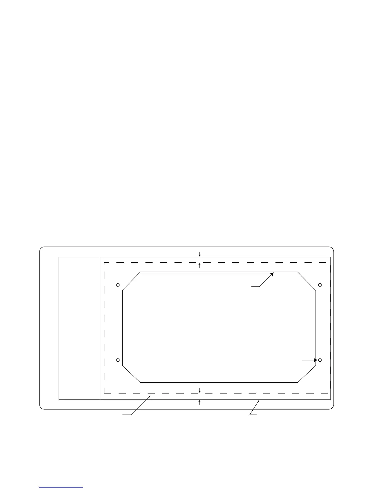
CUTTING TEMPLATE - AIR HANDLER
PART NO. 4002063
CUT OUT FOR AIR REGISTERS
DRILL 4 HOLES - 5 DIAMETER
NEW CUTTING LINE
10
10
OUTSIDE OF AIR HANDLER CABINET
CUT OUT FOR CONTROL BOX