4
Installing the Condenser set
Marking out the floor
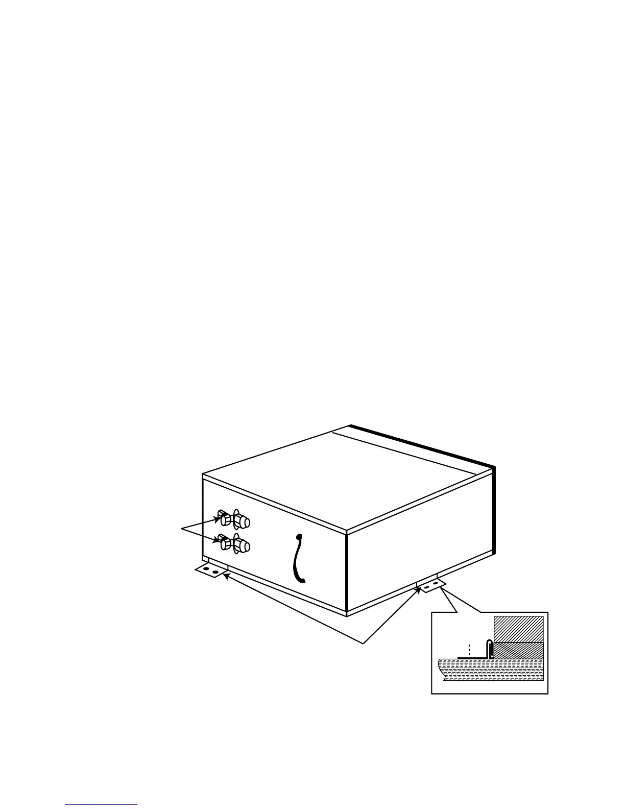
Use the floor template as provided (or refer to fig. 3). Both, or either end of the
con/set may be hard against a wall or panel, but the back of the unit must have
sufficient clearance to allow easy access to the line valves (see fig. 4). Once a
convenient position has been decided upon, place the template, side marked
“Inside Wall”, hard against the inside skin of the van, and mark out the six 114mm
diameter (4
1
/2”) condenser air inlet holes, and the square compressor well hole
(see fig. 3).
Note: Check to see if any structural floor members will interfere with any of these
holes. It is essential that the compressor well is unimpeded.
The air inlet holes will tolerate some obstruction. However the total area must not
be less than 75% of the inlet holes in the chassis.
We recommend that a hole saw be used to cut out the six round holes. If a
structural member is beneath, then the complete cut out can be removed. The gap
between the top of the structural member and the underside of the unit (i.e. the
floor thickness) will help in overcoming the restriction of the member.