Herrtronic
®
MD Series
Installation, Operation, & Maintenance Manual
20 www.herrmidifier-hvac.com
Maintenance
To maintain efciency of the unit, the water level in the cylinder
will slowly rise as the electrodes become coated with minerals.
Progressively, the water level reaches the cylinder full electrode,
representing the maximum allowable water level. Eventually, all
of the usable electrode surfaces will be coated. After the end
of cylinder life setpoint has been reached, the LCD will read
“End of Cylinder Life” fault. Cylinder replacement should occur
to maintain satisfactory humidity levels. “End of Cylinder Life”
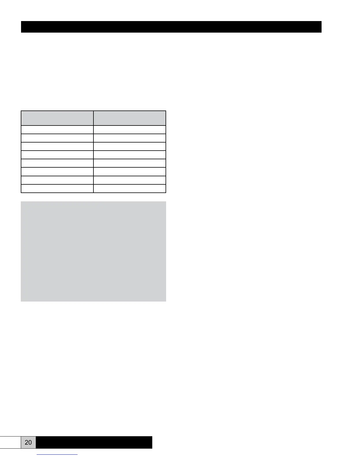
varies with water conductivity. Refer to the chart that follows:
Conductivity (micro-mhos)
(approximately)
Average Cylinder Life
(Hours)
70 2000
100 2000
135 1900
170 1800
250 1300
500 800
750 650
1000 500
NOTE
Many factors in addition to water conductivity effect cylinder
life. Total dissolved solids (TDS) and exact mineral content
of the water can have negative effects on cylinder life. Your
representative will be happy to review your water analysis.
If you don’t have an analysis and are on a municipal system,
the municipal water authority will provide one free of charge.
Conductivity between 70 and 200 micromho is best handled
with “on/off” control. Discuss your application with the factory
if your water is in this range and “Proportional” or “Propor-
tional + Integral” control is required. Water with less than 70
micromho may not be sufcient to allow the unit to operate.
Herrmidier has considerable experience optimizing the per-
formance of your humidier on “fringe” water conditions. Con-
sult your representative.
To Remove the Cylinder:
1. Turn the unit “off” by pressing the “on/off” button. Drain the
cylinder completely using the manual drain (Menu 5).
2. Disconnect the power to the unit..
3. Disconnect the electrode power wires (and jumpers if used)
- noting the orientation, and the cylinder full electrode wire
from the cylinder. Remove the expired cylinder from the
cabinet.
4. Position the new cylinder in the cabinet. Place the new “O”
ring as shown in Fig. 22. Lubricate the “O” ring with water
only and install cylinder into drain cup, EST-1062, pushing
down rmly with a twisting motion.
5. Reconnect the power wiring (and jumpers if required) refer-
ring to appropriate Figure on the next page that matches
the power wiring conguration of the unit. Be certain to use
lock washers on each electrode and tighten the electrode
knob (Fig. 25 or 29).
6. Installation is now complete, Reconnect power, turn unit
on, allow cylinder to ll and check for leaks. AFTER INI-
TIAL WARM UP, SHUT UNIT DOWN, TURN OFF MAIN
POWER AND RECHECK TIGHTNESS OF POWER CON-
NECTIONS WHILE UNIT IS WARM (TORQUE TO 15-20
in-lbs.).
Extended Shutdown:
The humidier is set by the factory to drain if the unit doesn’t
operate for seven days. However, the drain time can be revised
through reprogramming (Refer to Page 14). Always drain the
cylinder completely if it will be off of an extended period of time
(see Auto drain feature, menu 2, page 13).