Herrtronic
®
MD Series
Installation, Operation, & Maintenance Manual
27
www.herrmidifier-hvac.com
Inputs / Outputs of Terminal Strips and Terminal Block
Terminal Block
Position 1-6 24 RET (GND)
7-12 24 VAC
All twelve (12) positions should be utilized if the Room Dispersion Unit (RDU) is installed
RDU Terminal Strip – Connections to RDU only
Pole
1 24 RET (GND) (Always)
2 24 VAC Trigger (24 VAC when contactor is energized)
3 Line Voltage (Always)
4 Line Voltage (Always)
5 24 VAC Air (24 VAC when switch Proving Switch is closed)
6 24 VAC (Always)
Control Terminal Strip
Pole
1 24 VAC (Always)
2 Airow / High Limit input, 24 VAC for operation
3 External “Off”, 24 VAC for operation
4 Control input ground – Modulating and on/off
5 Control input signal – Modulating and on/off
6 +5 VDC
7 +20 VDC
8 Limit input ground - Modulating
9 Limit input signal - Modulating
10 +5 VDC
11 RS-485 Communication, Negative, Digital
12 RS-485 Communication, Positive, Digital
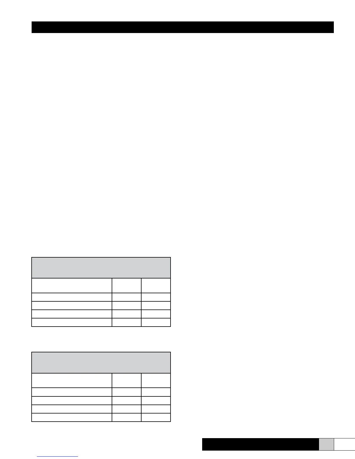
Figure 30
Hard Water/Softened Water*
(750-1000 Micromho)
Adjust Menu Items to These Settings
MDM MDS/
MDD
Cycle Time (Menu #3) 75 115
Low Drain Threshold (Menu #2) 88 84
Capacity Setpoint (Menu #2) 96 96
High Drain Threshold (Menu #3) 108 108
*Naturally soft water is less than 50 micromho.
Figure 31
Very Hard Water
(> 1000 Micromho)
Adjust Menu Items to These Settings
MDM MDS/
MDD
Cycle Time (Menu #3) 60 100
Low Drain Threshold (Menu #2) 91 86
Capacity Setpoint (Menu #2) 94 92
High Drain Threshold (Menu #3) 105 105