Herrtronic
®
MD Series
Installation, Operation, & Maintenance Manual
28 www.herrmidifier-hvac.com
NOTE
1. For On/Off (mode 1) units, a resistor (68.1 kohms) between poles 5 and 7 on the controls terminal strip is required.
(34.0 kohms for MDD units)
2. If more than one MDS, MDM or MDD are “networked” together, a resistor may be required in socket R28 on PCB.
(See pg.12)
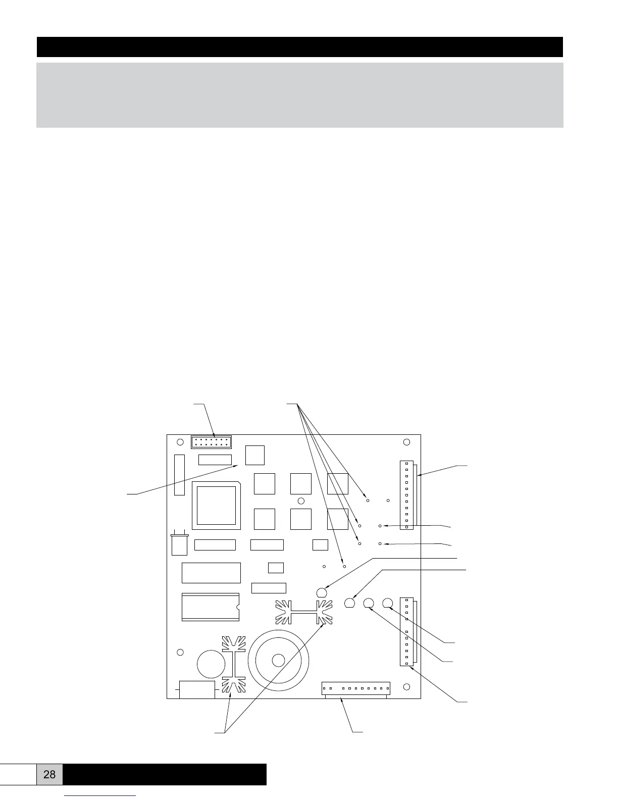
J3
J1
J5
1
11
J4
1
2
SW7
RESET
EPROM
RAM
CR1
CR2
CR4
CR5
R16
R28
R12
R7
CONTACTOR IND.
FAULT IND.
SW5 SW6
SW4
SW3
SW1
SW2
Microprocessor Board
FILL VALVE IND.
DRAIN VALVE IND.
J1 MOLEX
CONNECTOR
J5 MOLEX
CONNECTOR
J3 MOLEX
CONNECTOR
HEAT SINK
CAPACITY RESISTOR
RESET
SWITCH
SELECT
RESISTORS
RIBBON CABLE
CONNECTOR
HIGH LIMIT RESISTOR
Circuit Board: J1 Connector
PIN
4 Toroid Input, Non-polar
3 Toroid Input, Non-polar
2 RS-485 Communication, Positive, Digital
1 RS-485 Communication, Negative, Digital
5 Not Used
Circuit Board: J3 Connector
PIN
1 Power Input, 24 VAC
2 Power Input, 24 RET (GND)
3 Not Used
4 24 VAC, for contractor coil, (Always)
5 24 VAC, for contractor coil, switched
6 Alarm Output
7 Alarm Output
8 VAC, for drain valve, (Always)
9 24 VAC, for drain valve, switched
10 24 VAC, for ll valve, (Always)
11 24 VAC, for ll valve, switched
Circuit Board: J5 Connector
PIN
11. Door interlock input, 24 VAC to operate
10 Air ow/High Limit input, 24 VAC to operate
9 Auxiliary contact input, 24 VAC when energized and 0
VAC when de-energized.
8 Cylinder Full input
7 +5 VDC
6 Limit input signal – Modulating
5 Limit input ground – Modulating
4 +20 VDC
3 +5 VDC
2 Control input signal – Modulating and On/Off
1 Control input ground – Modulating and On/Off
Circuit Board: J3 Connector
PIN
1-14 LCD, 2-Lines X 20 Characters, non-backlit
Figure 32