Herrtronic
®
MD Series
Installation, Operation, & Maintenance Manual
23
www.herrmidifier-hvac.com
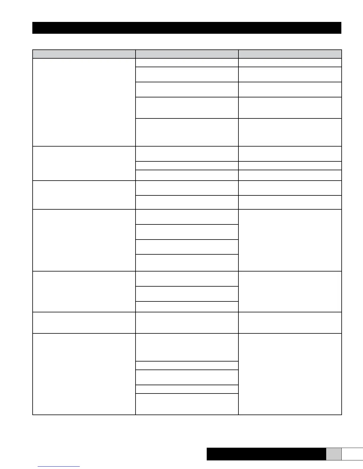
Unit Detected Faults (Red Light is Illuminated)
Problem / Symptom Probable Cause Reason - Correction
Overcurrent
When this condition occurs, the system
has sensed an excessive current draw
(138% of rated current) and has shut itself
down and drained completely to prevent
possible damage. The system has already
taken preventative action by attempting to
drain down prior to the fault condition oc-
curring. Therefore, further analysis is re-
quired before restart is attempted.
Restricted Drain System Clean and replace as necessary
Use of softened water without adjusting
operating parameters
See Fig. 30
Water conductivity in excess of 750
micromho
See Fig. 30 and 31
Expired steam cylinder – a mineral bridge
has developed allowing a short between
two electrodes.
Replace steam cylinder
If drain tempering is enabled and the rate
of ll is exceeding the rate of draining,
the tank will ll whenever the unit tries to
drain.
Adjust the ll valve metering screw to
slow the rate of ll so the unit can drain
properly. See Fig. 21 for adjusting screw
location.
Fill System Fault
The unit has been in ll cycle for 15 min-
utes continuously without reaching re-
quired output or cylinder full. System will
shutdown and drain completely.
Restricted or blocked ll system (strainer,
solenoid, external shut-off valve.)
Partially or completely open drain valve.
Extremely low conductivity supply water
End of Cylinder Life
The cylinder is full and humidier has not
been able to achieve desired output within
setpoint.
Cylinder expired-electrodes have been
consumed.
Replace
Extremely low conductivity supply water Add a 1/4 teaspoon of salt to the cylinder.
High Humidity
Humidity in the space being measured by
the control sensor has exceeded the pre-
set alarm level. This alarm is only avail-
able on units congured with P + I control
(mode 3).
Tampering with the control humidity set-
point.
1. Reset your alarm setpoint.
2. Turn off humidier at main disconnect
until humidication season.
Alarm set-point too close to control set-
point
Humidier is powered but not operating
and RH is above setpoint
Sensor or wiring has failed.
Low Humidity
Humidity in the space being measured
by the control sensor has dropped below
the preset alarm level. This alarm is only
available on units congured with P + I
control (mode 3).
Alarm setpoint too close to control set-
point
1. Turn the humidier “on” to satisfy de-
mand.
2. Adjust the low humidity alarm.
Humidier is powered but turned “off” and
the RH is below the alarm setpoint.
Sensor or wiring has failed
Slave Fault
One of the 6 indicating faults has been de-
tected in a slave unit.
Review of the slave units is required to
determine specic fault conditions.
Contactor Failed
Unit has tried to turn on but contactor has
not closed, or unit should be off, but con-
tactor is still closed.
Failed contactor - It’s common to nd
metal chips or other construction debris
lodged in the contactor preventing proper
operation
Repair or replace
Faulty control wiring.
Auxiliary contact dislodged from proper
position.
Faulty auxiliary contact
Installation with RDU’s--the jumper be-
tween control terminal strip poles 1 & 2
needs to be removed.