Herrtronic
®
MD Series
Installation, Operation, & Maintenance Manual
7
www.herrmidifier-hvac.com
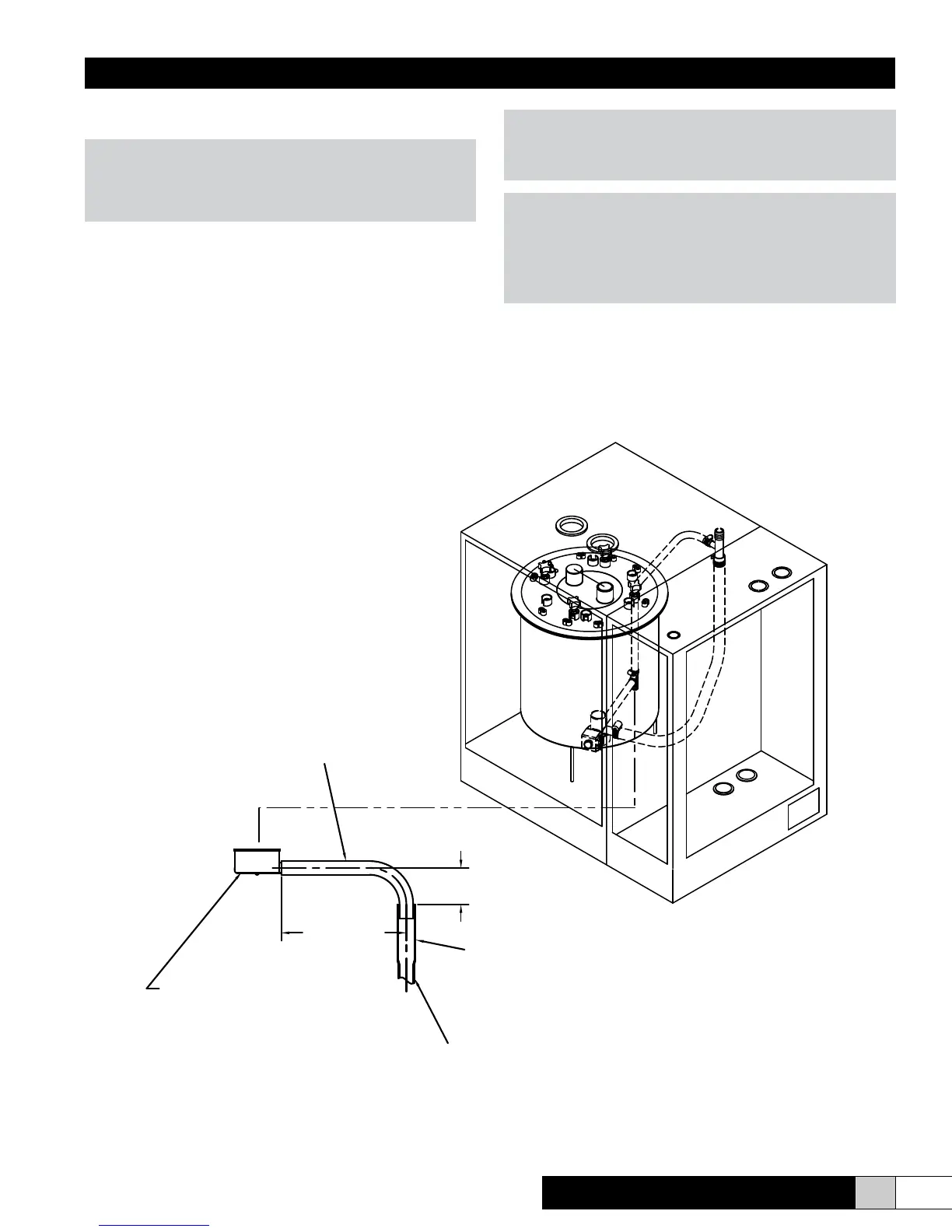
3. Connect the ¾” tube from the accessory pack to the drain
reservoir. Cut hose to necessary length.
WARNING!
Be sure that the ¾” drain tube is not kinked or bent in a man-
ner to prevent free owing drainage from the drain reservoir
to the drain pipe.
4. Insert the other end of the tube into a minimum 6” length of
1 ¼” minimum I.D. copper line. The balance of the drain
line should be 1” I.D. minimum with a minimum 1/8” per foot
slope. (See Figure 2)
WARNING!
If the drain line is exposed, it is recommended that it be in-
sulated for safety. Do not use PVC drain line unless “Drain
Tempering” is enabled (see page 16-17).
NOTE
Inlet water pressure must be in the range of 20-100 psig.
Consult the factory if you are outside this range. Softened wa-
ter may be used but requires that the low drain threshold be
adjusted (refer to Fig. 30 page 27). Drain water can be tem-
pered to lower its temperature (refer to page 16).
3/4" MIN. I.D./1" MAX O.D.
FLEXIBLE DRAIN CONNECTION
6" MIN. LENGTH OF 1-1/4" MIN. I.D.
COPPER LINE. IF PVC IS USED, LOCAL
CODES REQUIRE A LOWER TEMPERATURE
BALANCE OF DRAIN LINE TO BE 1" MIN. I.D.
WITH A MINIMUM PITCH OF 1/8" PER 12" OF RUN
DRAIN RESEVOIR
DRAIN WATER, ADD DRAIN TEMPERING.
4" RECOMMENDED
8"
RECOMMENDED
Figure 2