Do you have a question about the HES 9500 Series and is the answer not in the manual?
Steps for electrically connecting the strike and preparing it for installation.
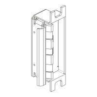
Instructions for preparing the door jamb using the installation template.
Connecting power wires and securing the strike to the jamb using provided screws.
Illustrates wiring for converting between 12V DC and 24V DC electric strike systems.
Details wiring configurations for the Latchbolt Monitor (LBM) feature.
Details wiring configurations for the Strike Monitor (LBSM) feature.
Instructions for converting the electric strike between Fail Secure and Fail Safe operation modes.
Provides critical measurements and dimensions for the 9500/9600 electric strike.
Details the process for adjusting the strike's horizontal position within the frame.