8
CONNECT ELECTRICAL WIRING
Connect all remaining wires (power supply, engine
start-stop, etc.) according to the wiring diagram of the
crane/machine and the radio remote control.
Quick-Disconnect Plugs
Hetronic offers a plug receptacle kit, which contains
two 12-pin quick-disconnect plugs with wedges and 28
contacts. The installer must wire the female
quick-disconnect plugs and terminate them to the
crane/machine controls.
Quick-Disconnect Plug Wire Terminations
Refer to the wiring diagram on this page, which is also
provided with your system.
The male and female connector module pins are
labeled. The 12 pin connectors use numeric
numbering, i.e. 1, 2, 3, 4, etc.
Receiver Wiring Diagram and Pin Layout
Each Hetronic radio remote control system is delivered
with two alkaline batteries. These are inserted in the
battery compartment located in the handle of the
transmitter.
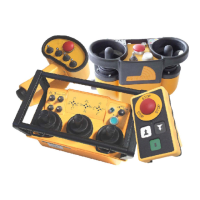
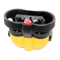
Please note that the actual configuration of each radio
remote control system may vary from the illustrations
shown in this manual. Refer to the technical
documentation provided with each system for the
actual design, layout and components.
FREQUENCY AND ADDRESS SETTINGS
Each Hetronic radio remote control system contains a
radio frequency (RF) unit. Each system consists of a
transmitter RF unit and a receiver RF unit.
Both Frequency and Address settings are uploaded to
the system using the new H-Link wireless technology.
These are preset at the factory and are password
protected. Refer to the HH-MFSHL H-Link
Programming Manual for more details.
IMPORTANT: The Address and Frequency settings for
both the transmitter and receiver must match;
otherwise, the system will not function.
R
a
d
i
o
R
e
m
o
t
e
R
e
c
e
i
v
e
r
M
F
S
H
L
-
D
C
1
6
-
P
W
M
+
1
2
/
2
4
V
D
C
C
o
n
t
r
o
l
C
i
r
c
u
i
t
F
1
1
0
A
K
0
G
N
D
(
-
)
P
W
M
1
P
W
M
2
K
3
K
4
K
5
K
6
K
7
K
8
K
9
K
1
0
M
C
Inputs
A
B
K
1
1
K
1
2
K
1
3
K
1
4
U
B
2
K
1
K
2
K
1
5
K
1
6
I
N
1
I
N
2
w
w
w
.
h
e
t
r
o
n
i
c
.
c
o
m
B
7
B
6
B
4
B
5
B
3
A
6
A
7
A
5
A
8
A
4
A
9
A
3
A
1
0
(
A
)
A
2
A
1
1
A
1
A
1
2
B
1
0
B
1
2
B
1
B
1
1
B
2
B
9
B
8
(A)
7
8
9
1
0
1
1
1
2
6
5
4
3
2
1
1
2
3
4
5
6
1
2
1
1
1
0
9
8
7
A
d
d
r
e
s
s
L
e
a
r
n
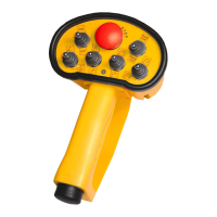
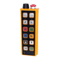
HAND-HELD TRANSMITTERS
CAUTION: AVOID INJURY OR DAMAGE -
Operating the transmitter without its antenna
could destroy the final stage of the RF
module. DO NOT attempt to change the
Hetronic pre-set frequency or the 20-bit
address. Personal injury and property
damage could result from transmission
interference and may void the warranty.
PRELIMINARY COPY
 Loading...