2
1. Controller description
The G422 controller is a device designed and made for controlling solar collector systems.
The product has been made with the use of modern and reliable microprocessor technology. Design of the controller is modern and the controller itself is
very user-friendly thanks to the use of a user panel with a clear keyboard and an LCD display.
General dimensions of the controller: 145mm 95mm 65mm.
An extensive basic option pack makes the controller extremely practical which is certainly of an advantage. These options include:
multiple system configurations,
displaying system diagram and animation of the working devices,
possibility of connecting the devices for monitoring the installation via a LAN module,
protecting the pump against damage resulting from lack of flow,
adjusting efficiency of the solar collector pump,
possibility of controlling manually all the devices connected to the controller,
calculating instantaneous power of a collector and summing up all the energy produced by solar collectors,
in-built real time clock.
controller memory after switching off the voltage
protection against freezing and overheating of solar collectors
the possibility of switching on night-time cooling and vacation option
switching off the LCD display in order to minimize energy consumption
2. Connecting external devices
The G422 controller has been equipped with 6 inputs making it possible to connect temperature sensors of the NTC10kΩ type, three inputs for connecting external devices,
pumps or three-way valves depending on the installation scheme chosen and two electronic flow meters. Moreover, the controller has been equipped with control of electric power
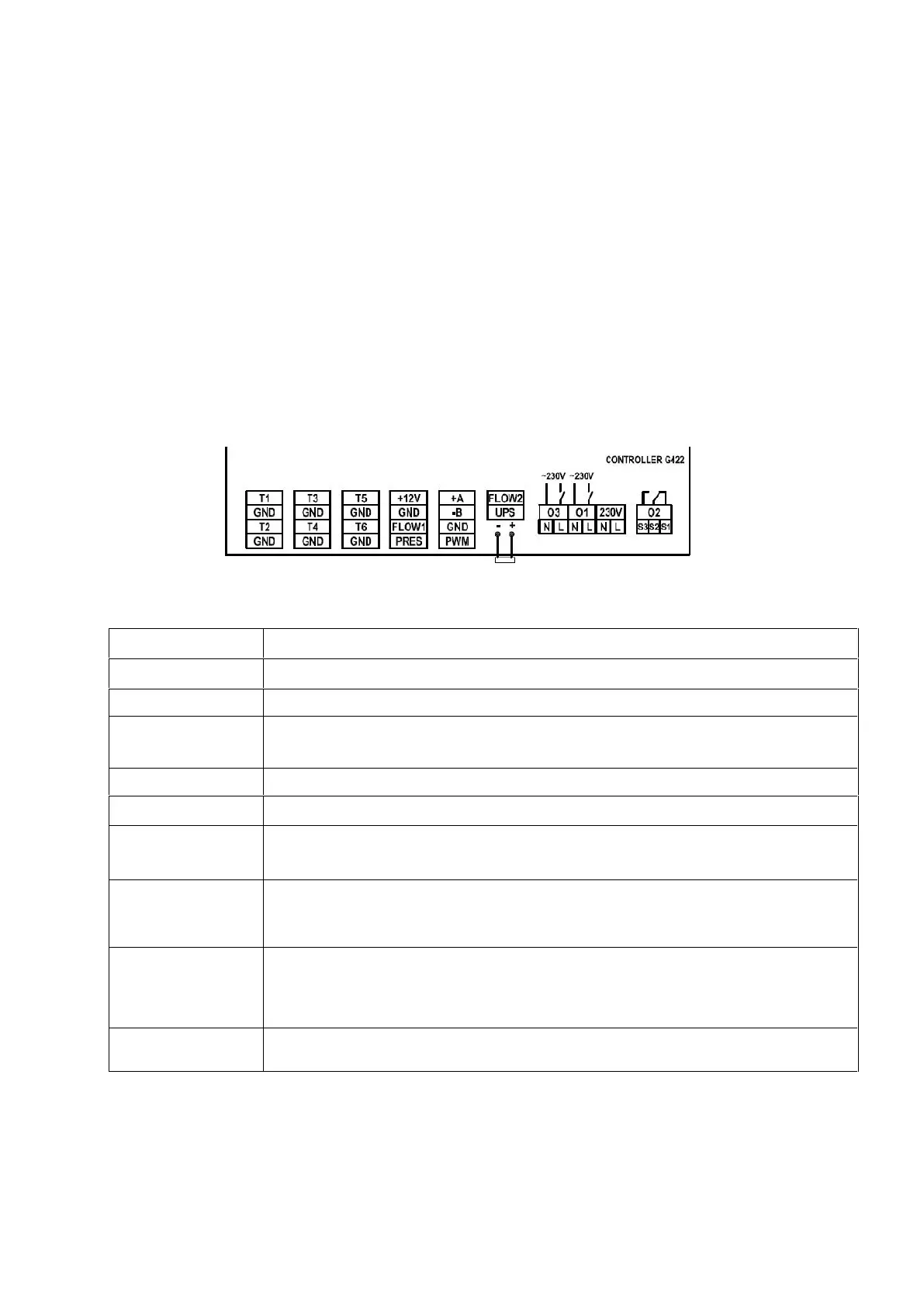
outages for UPS and ability to connect pressure switch. Graphical representation of outputs and inputs has been presented in Figure 1 whereas descriptions of controller inputs and
outputs have been presented in Table 1.
Fig. 1. Controller inputs and outputs
Connection to 230V~/50Hz mains – Maximum current intensity: 6A
Main pump input – Maximum current intensity: 2A
Transmitter output - no voltage output, (relay) – Maximum current intensity 2A
– S1-S2 – NC (normally closed), – S2-S3 – NO (normally open).
May operate as voltage output - applying voltage to S2 will result in changeover voltage output.
Transmitter output - no voltage output, (relay) – Maximum current intensity 2A
T1 – T6………….. Temperature sensor inputs - NTC10kΩ
GND……………… Ground input “-” for temperature sensors or other devices
+12V………………Constant voltage +12V for flowmeter no.1, no.2 or EKO-LAN modem
GND……………… Ground “-” for flowmeter no.1, no.2, EKO-LAN modem, pressure switch or control of electric power outages
FLOW1………………Flowmeter no.1 input
PRES……………… Pressure switch input
+A .........................RS485 communication input for connecting a communication device (e.g. EKOLAN modem).
-B..........................RS485 communication input for connecting a communication device (e.g. EKOLAN modem).
GND......................Ground output “-” for PWM pump control signal.
PWM.....................Positive output „+” for PWM pump control signal.
FLOW2.................pulse input for electronic flowmeter 2 series G-916
UPS ......................“control of electric power outages” input. Short-circuiting the UPS, GND terminals switches the controller to the
power saving mode for maintaining power supply (supplied from UPS). When in UPS mode, the P pump rotational speed symbol blinks
(additionally, when the P pump is active, 6 dots blink indicating that the P pump operates in 6
th
gear) and any additional devices
connected to the controller, except for the P collector pumps, are disabled (scheme 15 and 16 for the K pump).
+............................Titanium anode supply output – anode contact – applies to the G422-P09A controller only
-.............................Titanium anode supply output – water heater contact – applies to the G422-P09A controller only
Table 1. Controller inputs and outputs description.
When connecting any devices to controller outputs you need to remember that the outputs marked O1 and O3 are voltage outputs to which external devices can be connected
directly. The O2 output is a no voltage one and it must be connected in series between the power source and the external device.
ATTENTION !
If a power cord gets damaged it should be substituted with new one.
For specific installation schemes with the description of connecting devices to the controller, see section 4 (Installation schemes).
 Loading...