6
Fig. 7. Schematic and electrical diagram of installation no 5.
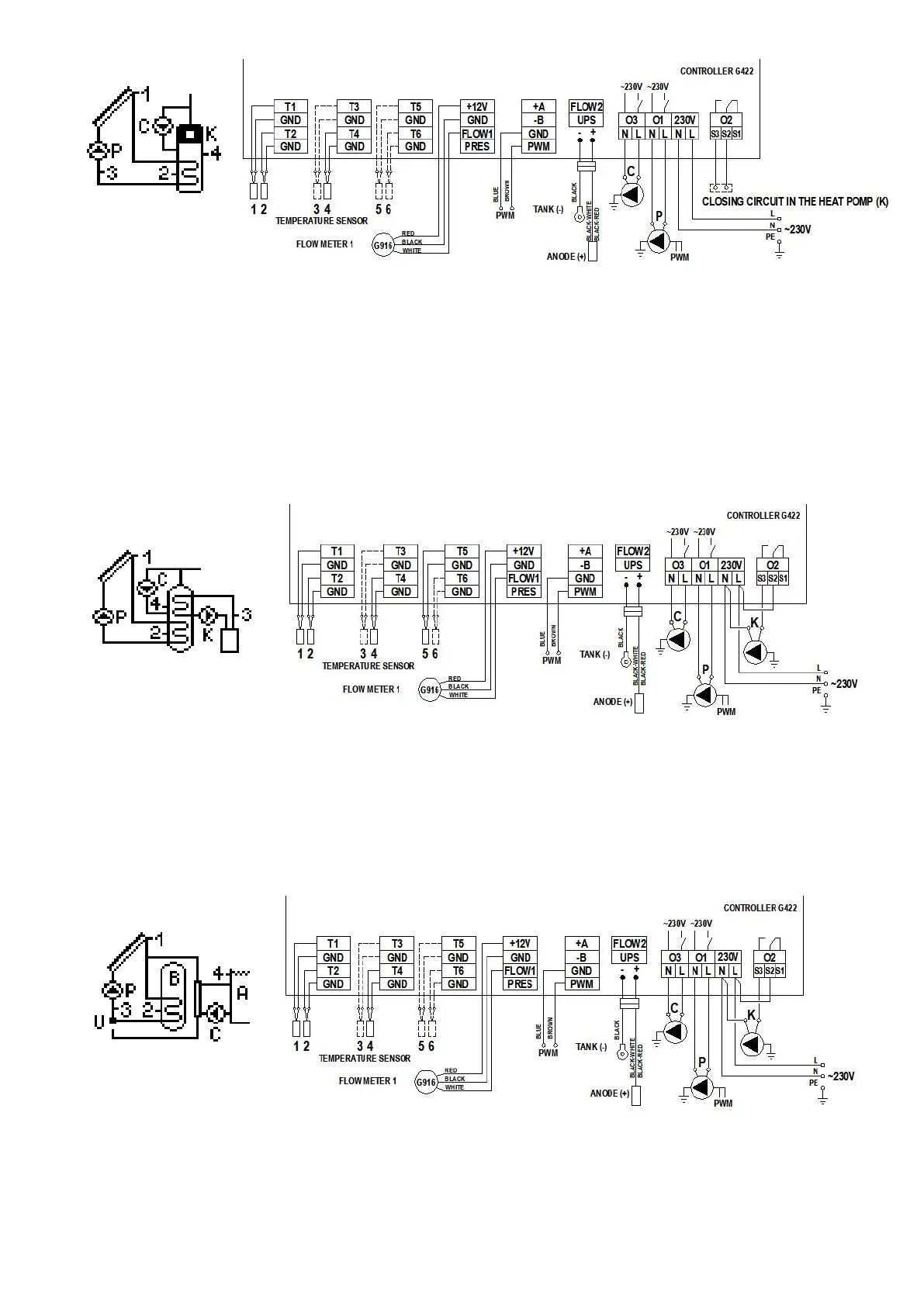
4.6 Tap water heating system - controlling solar collector pump, circulation pump, a fireplace pump or a solid-fuel boiler pump – scheme no 6
Controlling the P collector pump
Similarly as in scheme no 1 - description in point 4.1.
Controlling the C circulation pump
Similarly as in scheme no 2 - description in point 4.2.
Controlling K boiler pump
The K boiler pump will be switched on if the T5 temperature at the boiler outlet gets higher by the “Temperature difference ON add. pump, valve” value than the T4 temperature in
the upper part of the heater. The pump will remain switched on until the difference in temperatures (T5-T4) falls below the set value and the temperature in the heater reaches the set
value of “Max. temp. T4 OFF heat source”. Moreover K pump operation is limited by the “Min. temp. T5 ON Boiler pump” parameter. If the T5 temperature at boiler outlet is lower
than the set parameter value, the K pump remains off.
The K pump can operate in the “Overheating protection of the heater” mode. The K pump will be activated when the “Overheating protection of the tank” option is enabled and the T2
temperature in the lower part of the heater exceeds the "MaxTemp. T2 OFF collector's pump " parameter.
ATTENTION ! When the cooling function is active, the T2 temperature value flashes on the screen.
Fig. 8. Schematic and electrical diagram of installation no 6.
4.7 Double heater system - makes it possible to provide additional solar energy for the boiler heater with the use of a mixing pump - scheme no 7
Controlling the P collector pump
Similarly as in scheme no 1 - description in point 4.1.
Controlling the C circulation pump
Similarly as in scheme no 2 - description in point 4.2.
Controlling the K mixing pump
The K mixing pump will be switched on if the T2 temperature at the collector heater gets higher by the “Temperature difference ON add. pump, valve” value than the T4
temperature in the boiler heater. The pump will remain switched on until the difference in temperatures (T2-T4) falls below the set value and the temperature in the boiler heater
reaches the set allowable value of “Max. temp. T4 OFF heat source”.
Fig. 9. Schematic and electrical diagram of installation no 7.
4.8 Double heater system - makes it possible to provide additional solar energy heating for the boiler heater with the use of a circulation return - scheme no 8
Controlling the P collector pump
Similarly as in scheme no 1 - description in point 4.1.
Controlling the C circulation pump
Similarly as in scheme no 2 - description in point 4.2.
 Loading...