3
3. Switching on and using the controller
3.1 First switch on of the controller
Upon connecting the controller to a power source it will be switched on in the stand-by mode and a diode will get lit. In this mode the LCD display gets slightly back-lit and the current
controller software version appears on the screen. When the controller is in the stand-by mode you can switch it off with the button. During regular controller operation it is always
possible to get it back into the stand-by mode by pressing the button. In the standby mode all the inputs and sound alarms are switched off. Full description of the messages
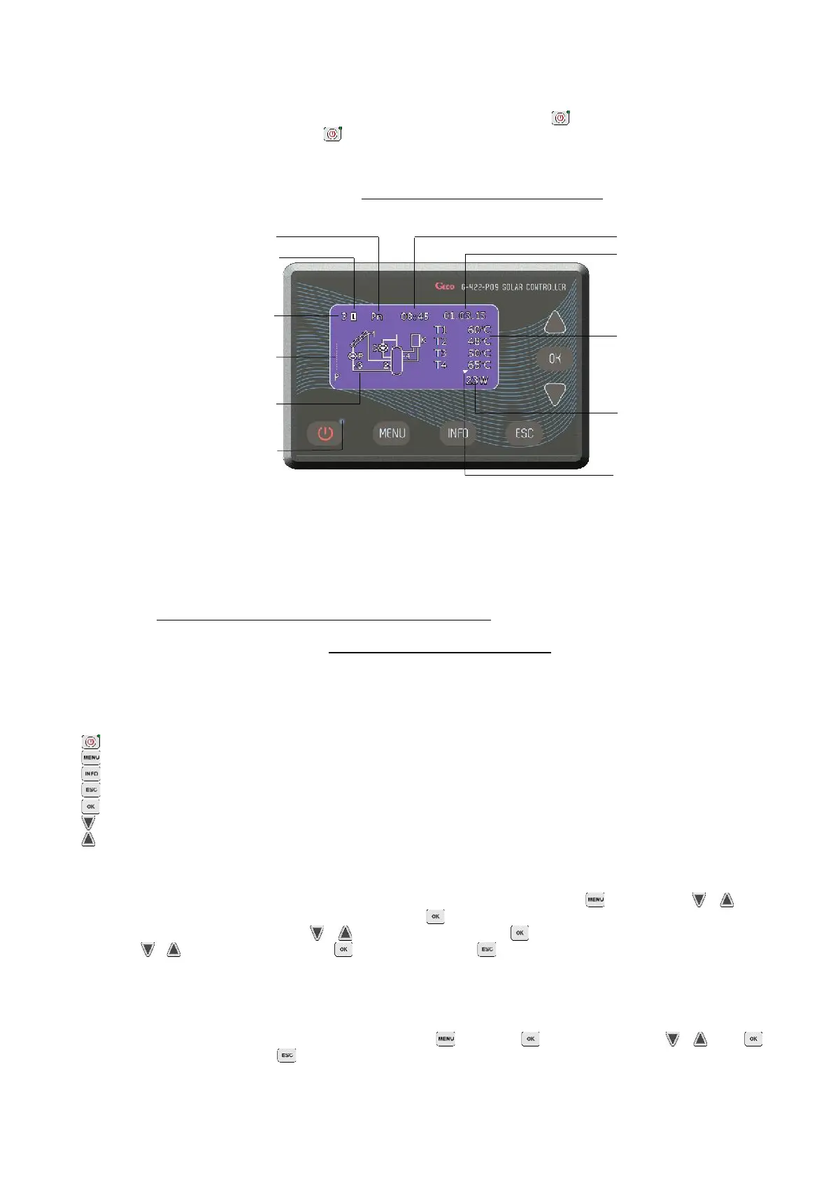
displayed on the controller screen has been presented in Figure 2.
ATTENTION ! The controller has a system password 0110 to secure its functions against unauthorised persons and children.
With the first switch on of the controller in a regular operation mode the keyboard and temperature sensors will get calibrated. During calibration it is strictly prohibited
to touch the controller keyboard as it may result in abnormal controller operation.
Fig. 2. Description of the basic screen on the LCD display
ATTENTION ! Remember to install temperature sensors correctly as described in the selected scheme. Change in sensor location might result in irregular operation of
the control system.
Insulate the points where sensors are connected with additional wires or insulate all blocks connecting sensors with wires.
When the collector pump is switched off or the T3 sensor on collector return is disconnected, dashes appear on the display in place of instantaneous power of the solar
collectors (- - - - -). The power calculation option is unavailable for the schemes no 10, 12, 15 and 16.
When the controller is in regular operation and during the blanking period no key is pressed, the LCD screen will be switched off. After pressing any key on the keyboard
the LCD back light will switch on for the blanking period set. Screen blanking aims at limiting energy consumption.
Connect the electrical plug to the socket equipped with a protective terminal and protected with RCD.
It is forbidden to install pump units in close vicinity of open flames, high temperatures and storage of flammable materials.
3.2 Controller keyboard description.
The controller has a touch keyboard with 7 keys which call the following functions:
- switching the controller on into regular operation or switching it off into the stand-by mode.
- entry into the controller MENU from the main screen level
- contact data
- cancelling all the controller operations or return to the previous screen
- confirming all the controller operations or moving to the next screen
- selection of all the controller options (down) or change (reduction) of all the values available for the controller
- selection of all the controller options (up) or change (increase) of all the values available for the controller
ATTENTION ! Excessive dirt on the display and the keyboard might result in irregular key operation.
3.3 Controller operation
If the controller has been switched into regular operation mode, you can access the main controller MENU by pressing the key. Navigation keys or serve the
purpose of selecting some options. Then you can enter the selected option by pressing the key.
In order to edit controller parameters use navigation keys or to select a given parameter and press to confirm parameter editing (the values will flash). Then use
navigation keys or to change the required value and press in order to accept it. By pressing you will return to the previous screen.
ATTENTION ! The operation scheme presented applies for almost all the controller options. After any changes of the scheme or parameters in the controller,
it is recommended to switch it off and then on again with ON/OFF button.
4. Installation schemes (scheme selection)
This option makes it possible to select an appropriate installation scheme necessary for correct operation of the controller. In order to select an installation scheme:
Press the following key combination: starting point - MAIN SCREEN: enter into the MENU , Select scheme , Select an appropriate scheme or , confirm (a
continuous sound signal), return to the main screen .
ATTENTION ! Broken lines in all the installation schemes refer to temperature sensors which can be connected to the controller, but are not required for its proper
operation for the selected scheme. Connection of titanium anode is marked on the diagrams (applies to the G422-P09A controller only)
 Loading...