4
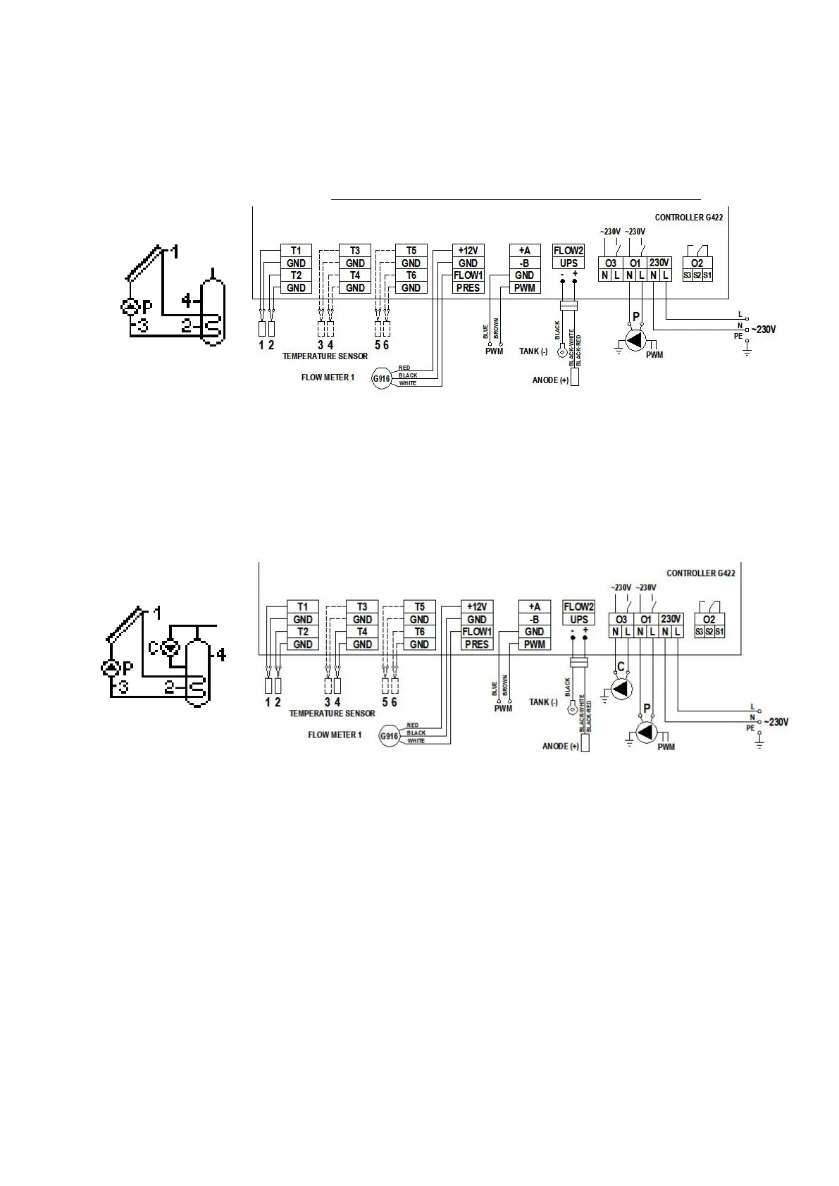
4.1 Tap water heating system - controlling solar collector pump – scheme no 1
Controlling the P collector pump - Regulation of collectors’ pump – scheme no 1
The P collector pump will be switched on if the T1 solar collector gets hotter by the “Temp. T1&T2 difference - pump ON” value than the T2 temperature in the lower part of the
heater. If the heater’s temperature reaches the set value of “MaxTemp. T2 OFF collector’s pump”, the P pump will be switched off. Additionally, in order to avoid unstable pump
operation when the temperature on the sensor changes, switch on and switch off hysteresis has been used.
Controlling the P collector pump - Regulation of collector’s pump - YES
Applies to the electronic pumps controlled with PWM signal only. When a normal circulation pump is connected, the pump will operate on an on/off basis although the
control is enabled.
The P collector pump will be switched on and off in the case described above but the collector changes the rotational speed of the P collector pump depending on the difference in temperature (T1-
T2) and the set parameter “Temp. T1&T2 difference - pump ON”. This option makes it possible to effectively collect energy from the collectors withvariable solar radiation.
Fig. 3. Schematic and electrical diagram of installation no 1.
4.2 Tap water heating system - controlling solar collector pump and a circulation pump - scheme no 2
Controlling the P collector pump
Similarly as in scheme no 1 - description in point 4.1.
Controlling the C circulation pump
The C circulation pump is only switched on in the time programmed by the user in the “Time program C” setting. The C pump can work in two modes set by the user, that is, continuous or
discontinuous(“Time of switching on the circulating pump”and“Time of switching off the circulating pump”)in the“Circulation param.”setting.
Moreover, C pump operation is limited by T4 temperature in the upper part of the heater; if the T4 temperature is lower thanthe set value of “Min.temp. T4switchingon the circulation pump” in
the“Circulation param.”setting.
C circulating pump operation mode can be selected in the “Parameter settings” menu.
Fig. 4. Schematic and electrical diagram of installation no 2.
4.3 Tap water heating system - controlling solar collector pump, circulation pump and a boiler - scheme no 3
Controlling the P collector pump
Similarly as in scheme no 1 - description in point 4.1.
Controlling the C circulation pump
Similarly as in scheme no 2 - description in point 4.2.
K boiler control for tap water heating
The K boiler is only switched on for water heating in the time programmed in the “Time program K” option to be found in the “Parameter settings” menu. The boiler will switch off if
the temperature of the upper part of the T4 heater is lower than the set “Max. temp. T4 OFF heat source”. If the temperature of water in the T4 heater reaches to set value of “Max.
temp. T4 OFF heat source”, the boiler will be switched off. Additionally, the controller makes it possible to make boiler operation independent of the solar collectors. Boiler may be
switched off if the calculated collector power is higher than the “Coll. power OFF boiler, heater, heat pump” value set in control parameters.
ATTENTION ! Connecting the T3 sensor is necessary for calculating collector instantaneous power.
Tap water boiler can be controlled in two ways.
1. Switching the boiler on with a fault of appropriate contacts inside the boiler.
2. Switching the boiler on with temperature sensor input in the boiler by simulation of appropriately selected resistors corresponding to boiler switch on and switch off
temperatures. An example of a table of resistances depending on the manufacturer of a given boiler has been presented in the table below.
ATTENTION ! The original tap water temperature sensor remains disconnected and replaced by 2-wire cable from the controller G422.
 Loading...