Do you have a question about the Hi-Link HLK-LD2410S and is the answer not in the manual?
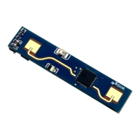
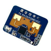
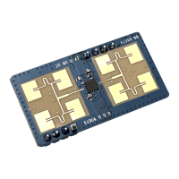
Shows the front and rear of the hardware LD2410S and its pin holes.
Explains how to debug the sensor firmware using a third-party serial port tool.
Introduces the use of the upper computer tool for understanding parameters.
Explains how to view current parameters and modify them for specific scenarios.
Details the 'Target Information' page for viewing detection results and real-time data.
Explains the steps to update the firmware of the MMwave sensor using the tool.
Outlines the basic procedure for entering command mode, setting parameters, and exiting.
Describes the formats of the data reported by the sensors in a table.
Command to read the sensor firmware version.
Command that must be sent before other configuration commands.
Command to stop parameter configuration mode and resume working mode.
Command to write the sensor's serial number.
Command to read the sensor's serial number.
Command used to set the general parameters of a sensor.
Command reads the configuration parameters of the sensor.
Command to set trigger and hold threshold parameters for distance gates.
Command reads the trigger and hold thresholds of the distance gate.
Command sets the trigger and hold SNR parameters of the sensor.
Command reads the trigger and hold SNR parameters of the sensor.
Shows the position of the millimeter wave sensor when mounted on a wall.
Requirements for the housing material and transmittance for the sensor.
Lists environments that can affect detection effect and cause interference.
Guidelines for ensuring correct sensor orientation, stability, and avoiding interference.
Precautions regarding input voltage range, ripple, and EMC compatibility.
States the maximum radial detection range and how distance is reported.
Discusses theoretical measuring error and factors causing accuracy fluctuations.
Explains the delayed reporting mechanism when no human body is detected.
| Brand | Hi-Link |
|---|---|
| Model | HLK-LD2410S |
| Category | Security Sensors |
| Language | English |