Page 32 pages in total
Shenzhen Hi-Link Electronic
Co.,Ltd
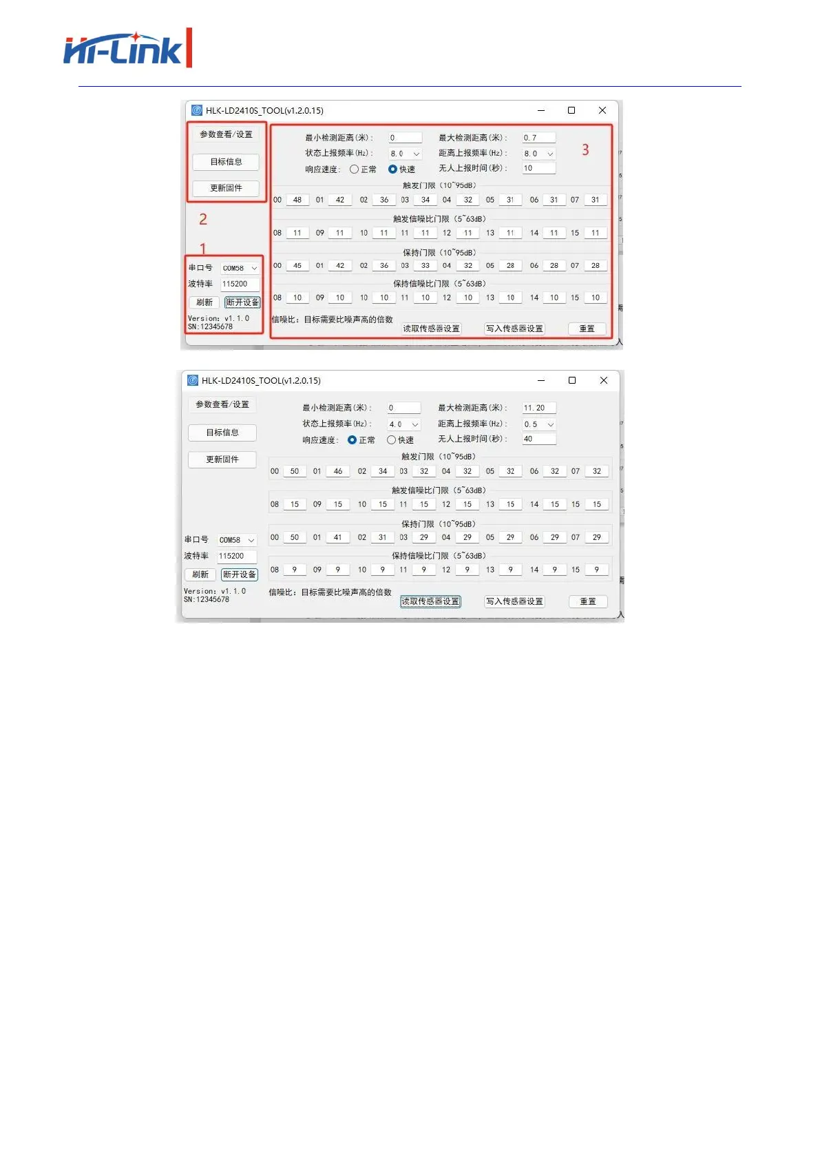
(a)Before device connection
(b)After device connection
Figure 4-2 HLK-LD2410S_TOOL
As shown in Figure 4-2(a), the upper computer tool interface can be divided into three areas:
Device operation area (Zone1), function button area (Zone2), and function page area (Zone3).
After the host tool is successfully connected to the MMwave sensor, the sensor firmware
version and sensor Serial Number (serial number) are displayed in the Zone1 area of the interface.
The default SN of the sensor is 12345678. The current parameter values of the millimeter wave
sensor are displayed in the View/Set Parameters area, as shown in Figure 4-2(b).
4.3. View/set parameters
On the page shown in Figure 4-3, you can view the current parameters of the MMwave sensor
and modify the parameters to meet the requirements of specific application scenarios.
The steps to read the parameters of the millimeter wave sensor using the upper computer tool
are as follows:
After connecting HLK-LD2410S to the upper computer tool, click the "Read sensor Settings"
button in the "Parameter view/Setting" function page, the page will pop up the "Read
 Loading...