November 2018
iCLASS SE® Express R10 Installation Guide
PLT-03681, Rev. A.22
Installation
1. Mount the backplate
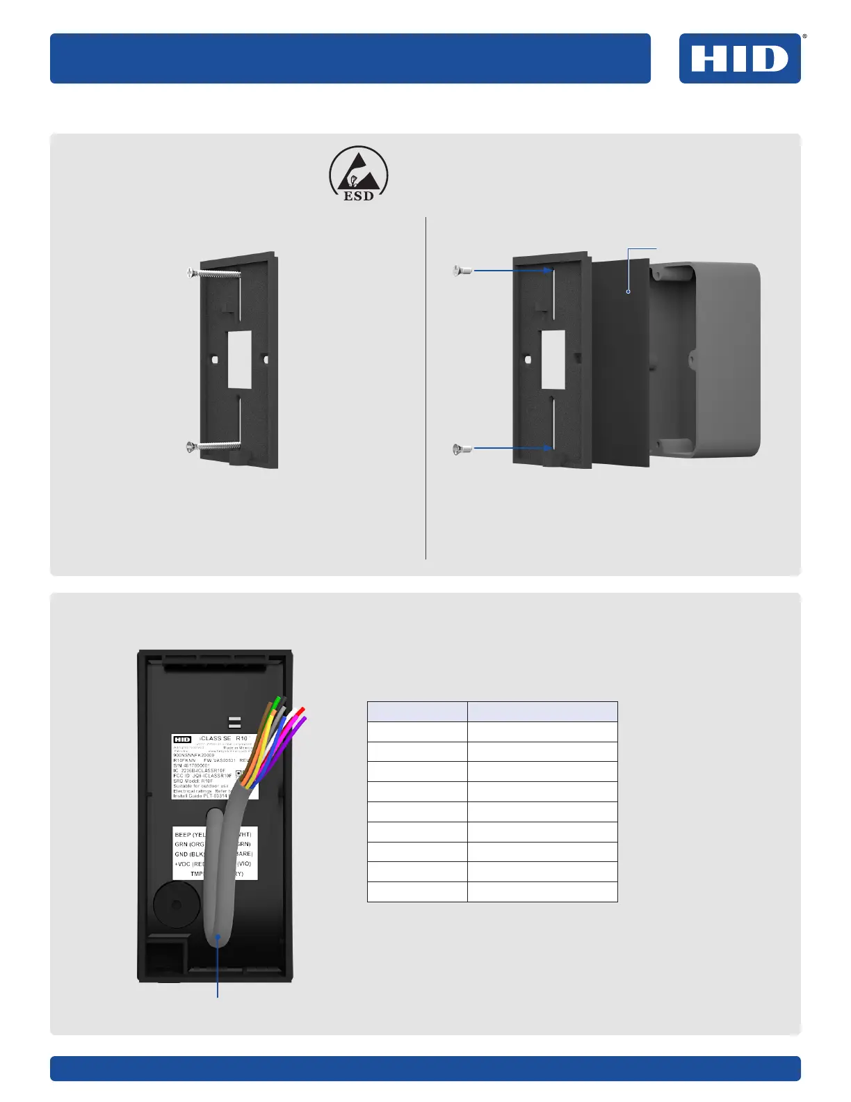
2. Wire the reader
ATTENTION
Observe precautions for handling
ELECTROSTATIC SENSITIVE DEVICES
Mounting directly to the wall/mullion mount
Use supplied 0.138-20 x 1.5" screws For Imperial (US):
Use supplied 0.138-32 x 0.375" screws
For Metric (EU etc):
Use supplied M3.5 x 12mm screws
Mounting to an enclosure (not supplied)
1
1
2
2
PIGTAIL DESCRIPTION
Yellow Beeper Input
Orange LED Input (GRN)
Black Ground (GRN)
Red +VDC
Drain Unused
Violet *Tamper #1
Violet/White *Tamper #2
White Wiegand Data 1
Green Wiegand Data 0
* Tamper Output. When activated or when the reader is
unpowered, the circuit between Tamper#1 and Tamper#2
reader control lines will open.
Note: Wiring the reader incorrectly may permanently
damage the reader.
9 in
(0.23m)
Optional gasket

 Loading...