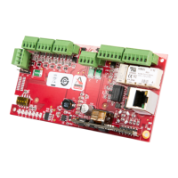
MaxiProx
®
Installation Guide Part No. 5375-901, Rev E.1
March 2012 Page 7 of 19
© 2008-2012 HID Global Corporation. All rights reserved.
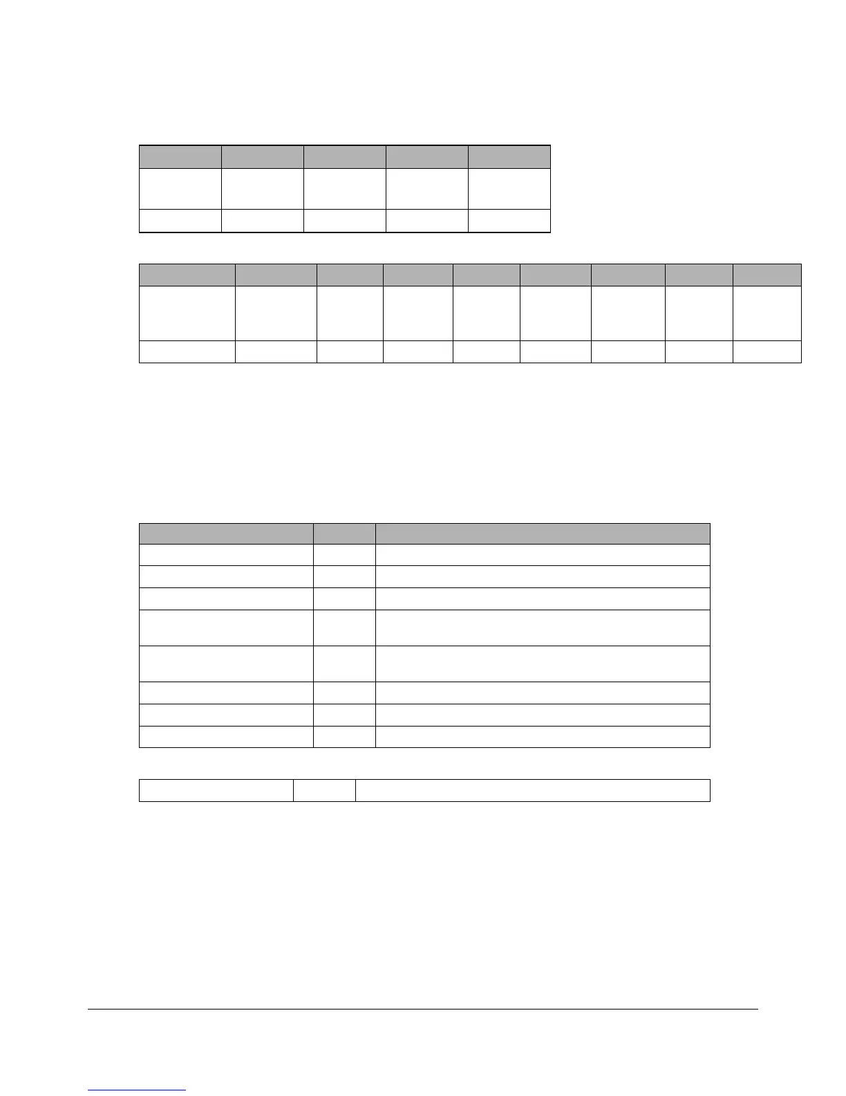
Table 1: TB1 Connector Definition
1 2 3 4 5
+DC
Shield
Ground
Ground
Tamper
Common
Tamper
Select
Red Drain Black --- ---
Table 2: TB2 Connector Definition
1 2 3 4 5 6 7 8 9
DATA 0
DATA/TD/RX+
DATA 1
CLK/RD/RX
DATA
RTN
GREEN
LED
RED
LED
BEEPER HOLD/
CARD
PRESENT
TX+
RS422
TX-
RS422
Green White Orange Brown Yellow Blue
Note: On TB2, pins 1, 2 and 7 have multiple purposes, depending on the configured reader interface.
In the above table, the first description is for Wiegand, the second for Clock-and-Data, the third for
RS232, and the fourth is for RS422.
2.7 Dip Switch and Jumper Settings
Verify the default settings according to the model ordered, or set the DIP Switches and Jumper
positions according to the following.
Table 3: DIP Switch and Jumper Settings
Switch Default Description
1. Interface mode 1 On See Table 6: Mode Chart
2. Interface mode 2 On See Table 6: Mode Chart
3. Interface mode 3 On See Table 6: Mode Chart
4. Beeper control On/Off On
On - beep after valid card read. Off - no beep after valid
card read.
5. Green LED flash Off
Off - flash after valid card read. On - no flash after valid
card read.
6. Single/Dual external LED Off Off - single line LED control. On - dual line LED control.
7. Serial Baud 1 control Off See Table 7: Baud Rate Chart – RS232 and RS422
8. Serial Baud 2 control Off See Table 7: Baud Rate Chart – RS232 and RS422
Table 4: Interface Jumpers Description - P3 and P4
P3 and P4 1-2 See Table 6: Mode Chart