Part No. 5375-901, Rev E.1 MaxiProx
®
Installation Guide
Page 8 of 19 March 2012
© 2008 - 2012 HID Global Corporation. All rights reserved.
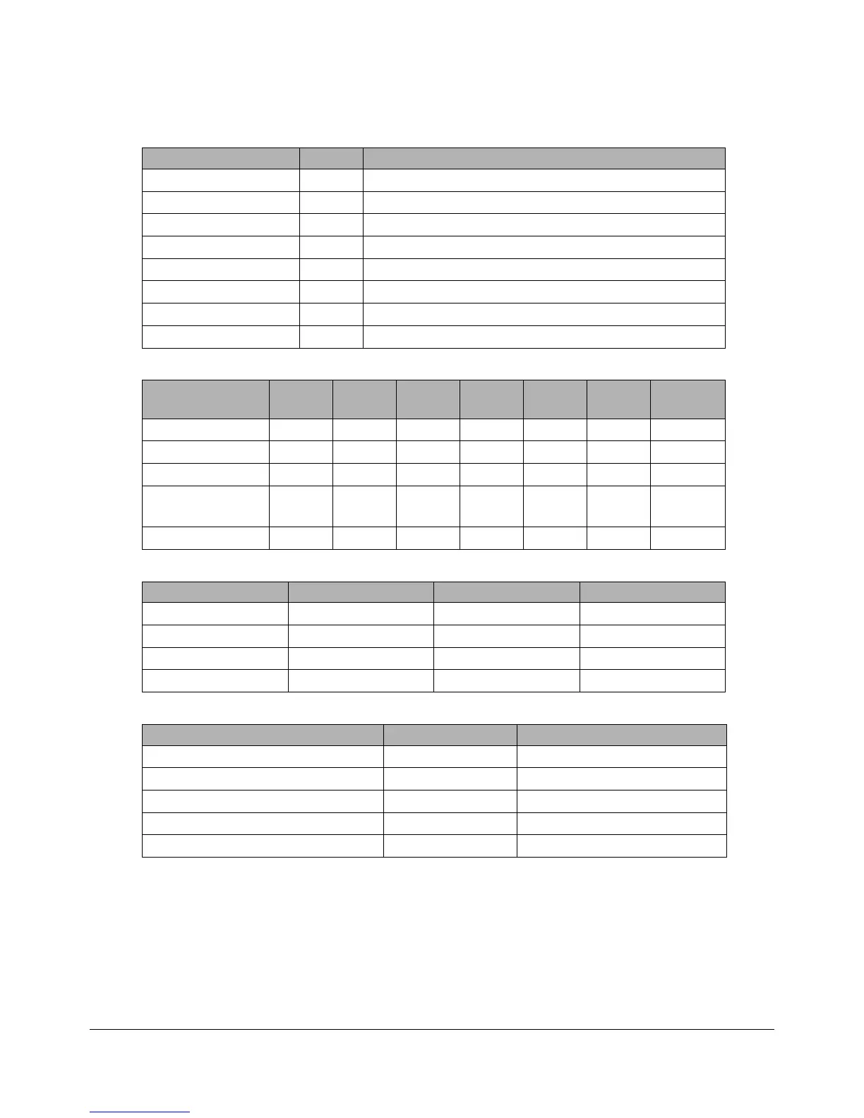
Table 5: Switch Description - SW2
Switch Default Description
1. Serial Baud 3 control On See Table 7: Baud Rate Chart – RS232 and RS422
2. Note address 0 N/A Unused
3. Note address 1 N/A Unused
4. Note address 2 N/A Unused
5. Note address 3 N/A Unused
6. Note address 4 N/A Unused
7. Unused
8. Unused
Table 6: Mode Chart
Mode SW1-1 SW1-2 SW1-3 SW5-3 SW5-4 SW5-5
P3 & P4
Jumpers
Wiegand ON ON ON NA NA NA 1-2
Clock-and-Data OFF ON ON NA NA NA 1-2
RS232 ON OFF ON NA OFF OFF 2-3
RS422
terminated
OFF OFF ON ON OFF OFF 2-3
RS422 unterm. OFF OFF ON OFF OFF OFF 2-3
Table 7: Baud Rate Chart – RS232 and RS422
BAUD SW1-7 SW1-8 SW2-1
9600 ON ON ON
4800 OFF ON ON
2400 ON OFF ON
1200 OFF OFF ON
Table 8: Switch Description - SW5
Switch Default Description
1. Data Isolation 1 On See 1 below
2. Data Isolation 0 On See 1 below
3. RS422 Terminating Resistor On See 5 below
4. Serial Hardware line setting 1 Off See 6 below
5. Serial Hardware line setting 2 Off See 7 below
1. Open Collector Data Outputs SW5-1&2 when using Wiegand or Clock & Data Interface.
Configure the data outputs so the MaxiProx is electrically isolated from the Host pull-up resistors.
The default (standard) configuration is non-isolated outputs; switches SW5-1 & 2 are ON.
Note: When configuring the outputs as isolated, use separate power supplies for the MaxiProx and
Host. These switches are unused when in RS232 or RS422 mode.