Rev. A 07-2018
33
06 08 10 14 16
V/~/Hz 230/1/50 230/1/50
230/1/50
400/3+N50 400/3+N50
V/~/Hz 24 V 24 V 24 V 24 V 24 V
V/~/Hz 230/1/50 230/1/50 230/1/50 230/1/50 230/1/50
V/~/Hz 230/1/50 230/1/50 230/1/50 230/1/50 230/1/50
mm
2
1,54444
mm
2
1,54444
21 26 31 36 41
V/~/Hz
400/3+N/50 400/3+N/50
400/3/50 400/3/50 400/3/50
V/~/Hz 24 V 24 V 24 V 24 V 24 V
V/~/Hz 230/1/50 230/1/50 230/1/50 230/1/50 230/1/50
V/~/Hz 400/3/50 400/3/50 400/3/50 400/3/50 400/3/50
mm
2
6 6 10 10 16
mm
2
6 6 10 10 16
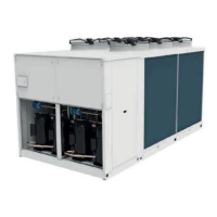
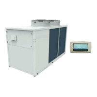
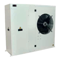
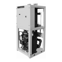
MTEC.3630.GB-A-1 Operation and maintenance manual LSA series English
LSA/HP+LJKHI¿FLHQF\DLUWRZDWHUKHDWSXPSV
4.20 Electric data
The electrical data reported below refer to the standard unit without accessories.
In all other cases refer to the data reported in the attached electrical wiring diagrams.
7KHOLQHYROWDJHÀXFWXDWLRQVFDQQRWEHPRUHWKDQRIWKHQRPLQDOYDOXHZKLOHWKHYROWDJHXQEDODQFHEHWZHHQ
RQHSKDVHDQGDQRWKHUFDQQRWH[FHHGDFFRUGLQJWR(1,IWKRVHWROHUDQFHVVKRXOGQRWEHUHVSHFWHG
please contact our Company.
Model
Power supply
Control board
Auxiliary circuit
Fans power supply
Line section
PE section
Model
Power supply
Control board
Auxiliary circuit
Fans power supply
Line section
PE section
Electric data may change for updating without notice. It is therefore necessary to refer always to the wiring diagram
present in the units.