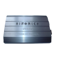
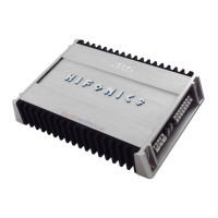
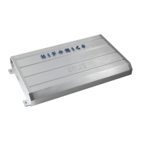
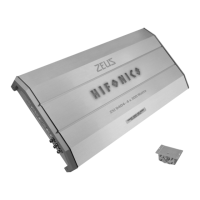
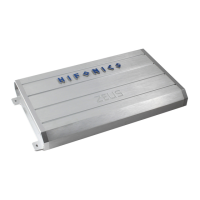
Do you have a question about the Hifonics Zeus Evolution ZXE2000 and is the answer not in the manual?
Crucial safety and placement advice before installing the amplifier, covering ventilation and cable separation.
Detailed steps for connecting the amplifier's power, ground, and remote turn-on wires for safe operation.
Guidance on connecting speakers, ensuring correct impedance and avoiding chassis shorts.
Recommendations for routing audio cables separately from power cables to prevent interference.
Explanation of using speaker wire inputs and the automatic turn-on function via voltage detection.
Procedure for setting the input level to achieve optimal signal without distortion.
Instructions for adjusting the subsonic and low pass filters for precise sound tuning.
Guidance on using the bass boost for enhancement and phase shift for acoustic matching.
Information on connecting and using the remote controller for adjusting bass levels.
Explanation of linking two identical amplifiers for increased power output and shared settings.
Visual representations of various connection setups, including mono configurations.
Details on the amplifier's protection circuit, LED indicators, and troubleshooting common faults.
Verifies proper connections, fuses, and voltage levels for correct amplifier operation.
Diagnoses issues indicated by a red LED, such as speaker shorts, overheating, or low impedance.
Guides on testing RCA inputs and cable integrity to ensure audio signal transmission.
Steps to resolve popping noises during turn-on, potentially using a delay turn-on module.
Addresses excess engine noise by examining signal routing, grounding, and vehicle electrical components.
| Channels | 1 |
|---|---|
| Signal-to-Noise Ratio | >95dB |
| Bass Boost Frequency | 45Hz |
| Fuse Rating | 200A |
| RMS Power at 1 Ohm | 2000 Watts x 1 Channel @ 1 Ohm |
| Power Output (RMS) | 2000 Watts |
| Peak Power | 4000 Watts |
| Subsonic Filter | 10Hz - 40Hz |
| Input Sensitivity | 0.2V - 6V |
| Phase Shift | 0° - 180° |


