This document outlines the features, installation, and menu operations for the HIKVISION TURBO HD H1T Series Bullet & Turret Cameras. These cameras are designed for both indoor and outdoor surveillance applications, including roads, warehouses, underground parking lots, and bars.
Function Description
The HIKVISION TURBO HD H1T Series cameras are high-performance surveillance devices equipped with CMOS sensors, providing clear images even in low-light conditions. They feature an IR cut filter with auto switch, enabling seamless transition between day and night modes. The cameras support OSD (On-Screen Display) menus for easy configuration of various parameters, including exposure, white balance, and video settings. Internal synchronization ensures stable operation, while the SMART IR mode intelligently adjusts infrared light intensity to prevent overexposure. Some models also support Power over Coaxial (PoC) functionality, simplifying installation by delivering power and video over a single coaxial cable. The 3-axis adjustment feature allows for flexible positioning and precise aiming of the camera.
Usage Features
Installation:
The cameras offer versatile installation options, including ceiling mounting with or without a junction box. Both wall mounting and ceiling mounting are suitable, with ceiling mounting serving as a reference for wall mounting instructions.
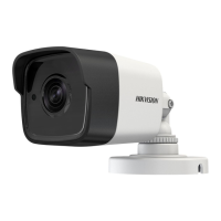
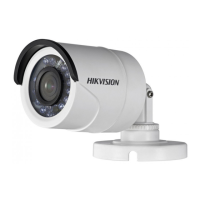
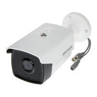
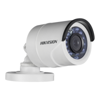
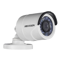
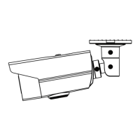
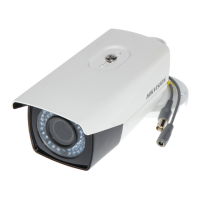
For Type I Cameras (Bullet Camera) without a Junction Box:
- A drill template is provided to mark screw holes and an optional cable hole on the ceiling.
- Cables can be routed through the cable hole or a side opening.
- The camera is then fixed to the ceiling using supplied screws. For cement walls, expansion bolts are required, while self-tapping screws are used for wooden walls.
- After connecting power and video cables, the camera is powered on to verify the image quality and adjust the surveillance angle.
- The 3-axis adjustment allows for precise control over pan (0° to 360°), tilt (0° to 90°), and rotation (0° to 360°) positions by loosening and tightening specific adjusting screws.
For Type I Cameras (Bullet Camera) with a Junction Box:
- A junction box (purchased separately) is used. Its drill template guides the marking of screw holes and an optional cable hole on the ceiling.
- The junction box is disassembled, and the camera's screw holes are aligned with those on the junction box's cover.
- The camera is fixed to the junction box's cover.
- The junction box's body is then attached to the ceiling, and the junction box cover is combined with its body.
- Cables are routed through the junction box, and the installation is completed by following similar steps to the non-junction box method.
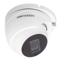
For Type II Cameras (Turret Camera) without a Junction Box:
- A drill template is used to mark screw holes and an optional cable hole on the ceiling.
- Screws are loosened to remove the clip plate and take out the main body of the camera.
- The mounting base is fixed to the ceiling with supplied screws (expansion bolts for cement, self-tapping for wood).
- Cables are routed through the cable hole or side opening.
- The main body is installed onto the mounting base, and the clip plate is inserted.
- Screws are tightened, and power/video cables are connected.
- The camera is powered on, and the image is checked. Adjustments for pan (0° to 360°), tilt (0° to 75°), and rotation (0° to 360°) are made by rotating the camera body and enclosure.
For Type II Cameras (Turret Camera) with a Junction Box:
- A junction box (purchased separately) is used, and its drill template guides the marking of screw holes and an optional cable hole on the ceiling.
- The camera's main body is removed, and the junction box is disassembled.
- The camera's screw holes are aligned with those on the junction box's cover, and the camera's mounting base is fixed to the cover.
- The junction box's body is secured to the ceiling, and the junction box cover is combined with its body.
- The remaining steps for cable connection and image adjustment are similar to the non-junction box method.
Menu Description:
The camera menu can be accessed via the PTZ Control interface by clicking a specific button or calling preset No. 95.
- Connect the camera to a TVI DVR and monitor.
- Power on all devices to view the image.
- Enter the PTZ Control interface.
- Call the camera menu.
- Use direction arrows to navigate: up/down to select items, Iris+ to confirm, and left/right to adjust values.
OUTPUT MODE:
In this submenu, users can configure:
- RESOLUTION: Set to 5 megapixels, 4 megapixels, or 1080p. Higher resolution provides a finer image.
- FRAME RATE: Adjust the number of images output per second. For 5 megapixels, options are 20 fps or 12.5 fps. For 4 megapixels, options are 25 fps or 30 fps.
- NTSC/PAL: Select the appropriate color encoding system (PAL for most countries, NTSC for North America, parts of South America, etc.).
FOCUS:
The FOCUS submenu allows for adjustment of the camera's focus using FOCUS+, FOCUS-, ZOOM+, and ZOOM- controls.
LANGUAGE:
The camera supports English and Chinese languages.
SET UP:
This submenu contains various image-related settings.
EXPOSURE:
Adjusts brightness-related parameters:
- BRIGHTNESS: Sets the overall brightness of the image (values 1 to 10).
- EXPOSURE MODE:
- GLOBAL: Normal exposure mode based on the whole image brightness.
- BLC (Backlight Compensation): Compensates for bright front objects, but may overexpose the background. BLC level can be adjusted from 0 to 8.
- GAIN: Optimizes image clarity in low light (HIGH, MEDIUM, LOW, or OFF). Note that noise may be amplified when GAIN is on.
- DWDR (Digital Wide Dynamic Range): Provides clear images in backlight conditions by balancing brightness levels in very bright and very dark areas (ON or OFF).
- ANTI-FLICKER: Prevents image flickering (ON or OFF).
WHITE BALANCE:
Adjusts color temperature to remove unrealistic color casts:
- ATW (Auto Tracking White Balance): Automatically adjusts white balance based on scene illumination.
- MWB (Manual White Balance): Allows manual adjustment of R GAIN/B GAIN values (1 to 255) to control red/blue color shades.
DAY/NIGHT:
Configures how the camera handles different lighting conditions:
- COLOR: Image remains colored at all times.
- B/W (Black and White): Image is black and white, and IR LED turns on in low light.
- AUTO: Automatically switches between Color and B/W based on scene brightness.
- INFRARED: Turns IR LED on/off.
- SMART IR: Adjusts IR intensity (1 to 3) to prevent overexposure. Higher values provide more pronounced effects.
VIDEO SETTINGS:
Adjusts various video parameters:
- CONTRAST: Enhances color and light differences (values 1 to 10).
- SHARPNESS: Determines image detail (values 1 to 10).
- COLOR GAIN: Adjusts color saturation (values 1 to 10).
- DNR (Digital Noise Reduction): Decreases noise, especially in low light and with moving images (values 1 to 10).
- MIRROR: Flips the image:
- DEFAULT: Mirror function disabled.
- H: Flips horizontally (180°).
- V: Flips vertically (180°).
- HV: Flips both horizontally and vertically (180°).
RESET:
Resets all settings to default values.
SAVE & EXIT:
Saves current settings and exits the menu.
Maintenance Features
Safety Instructions:
To ensure proper and safe use, users must adhere to "Warnings" and "Cautions."
- Warnings highlight potential serious injury or death if neglected. Key warnings include:
- Strict compliance with electrical safety regulations.
- Input voltage must meet SELV and Limited Power Source standards (12 VDC, IEC60950-1).
- Avoid connecting multiple devices to a single power adapter to prevent overload and fire hazards.
- Ensure plugs are firmly connected to power sockets.
- Securely fix the device during wall or ceiling mounting.
- Immediately power off and unplug the device if smoke, odor, or noise occurs, and contact the service center.
- Never attempt to disassemble the camera without professional assistance.
- Cautions highlight potential injury or equipment damage if neglected. Key cautions include:
- Avoid dropping the camera or subjecting it to physical shock.
- Do not place the camera in extreme temperatures (-40°C to 60°C), dusty, damp locations, or expose it to high electromagnetic radiation.
- Do not touch sensor modules with fingers.
- Clean gently with a clean cloth and a bit of ethanol if necessary.
- Do not aim the camera at the sun or other extremely bright places.
- Ensure the sensor is not exposed to laser beams when laser equipment is in use, as it may burn out the sensor.
- Maintain good ventilation to avoid heat accumulation.
- Keep non-waterproof devices away from liquids.
- Pack the camera in its original packing or similar texture during delivery.
Regulatory Compliance:
The device complies with FCC regulations (Part 15, Class A digital device), meaning it has been tested and found to meet limits for commercial environments. It also adheres to EU Conformity Statements (CE mark, Low Voltage Directive 2014/35/EU, EMC Directive 2014/30/EU) and Industry Canada ICES-003 (A)/NMB-3(A) standards.
- WEEE Directive (2012/19/EU): Products marked with the crossed-out wheelie bin symbol should not be disposed of as unsorted municipal waste. Proper recycling involves returning the product to the supplier or designated collection points.
- Battery Directive (2006/66/EC): Products containing batteries (marked with the same symbol, potentially including Cd, Pb, or Hg) should also be recycled properly through suppliers or collection points.
Pre-Installation Checks:
Before installation, users should:
- Verify that the device and all assembly parts are in good condition.
- Ensure all related equipment is powered off.
- Check product specifications for the installation environment.
- Confirm that the power supply matches the output to prevent damage.
- Ensure the mounting surface can withstand at least three times the camera's weight.
- Contact the dealer or service center if the product malfunctions, and do not attempt self-repair.