Unmanaged PoE Switch/User Manual
7
communicate with each other.
When several IP cameras are connected to the switch, this mode is recommended. To ensure the fluency of the monitoring
pictures, connect the G1 port and SFP1 port to the uplink device connected to a monitoring computer.
Standard
Default mode. In this mode, the switch is an ordinary switch, and all ports can communicate with each other.
Isolate
In this mode, all downlink ports of the switch cannot communicate with each other and can only communicate with G1
port and SFP port respectively.
Extend
In this mode, all ports can communicate with each other. In addition, the transmission rate of the ports 9 - 16 of
DS-3E0318P-E/M and ports 17 - 24 of DS-3E0326P-E/M reduces to 10 Mbps. The maximum transmission distance is up
to 250 meters.
In EXTEND mode, to ensure timely video data transmission, set the Data Rate to a value less than 8 Mbps.
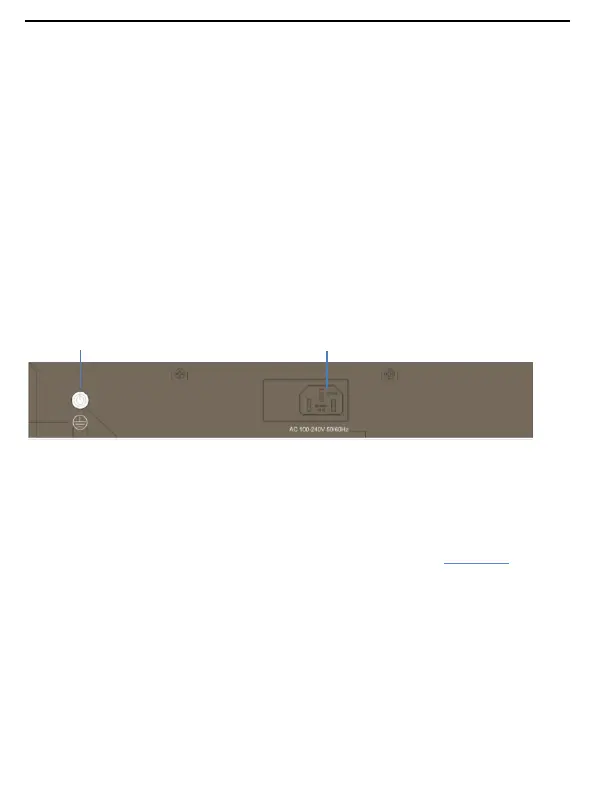
Rear Panel
DS-3E0318P-E/M or DS-3E0326P-E/M
Power Jack
The power jack is used to connect the switch to a power supply using the included power core.
Grounding Terminal
Used for connecting the grounding cable for lightning protection. For details, refer to section “2.3 Grounding”.
 Loading...