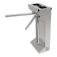
This document describes the DS-K3G411X Series Tripod Turnstile, a device designed to manage and detect unauthorized entrance or exit in various environments. It integrates with access control systems, requiring authentication via IC or ID card swiping, QR code scanning, or other methods for passage. The turnstile is suitable for locations such as attractions, stadiums, construction sites, and residences.
Function Description
The tripod turnstile's primary function is access control, ensuring that only authenticated individuals can pass. It supports bidirectional movement (entering and exiting) and can be remotely controlled and managed using HCP software. High-brightness LEDs indicate the entrance/exit and current passing status, providing clear visual cues to users. In emergency situations, such as a fire alarm, the turnstile arms automatically drop to facilitate evacuation. The device also supports configuration via a PC web browser for ease of management and offers ISAPI protocol support for third-party integration development.
Important Technical Specifications
The turnstile's physical dimensions are 202 mm x 550 mm x 1010 mm (width x depth x height), with a pedestal width of 34.9 mm. The distance between the nearest two pedestals is 781 mm.
Power Supply:
The device requires an AC power input, referred to as "High Voltage" in the wiring diagrams. It supports both 220 V and 110 V input voltages, selectable via a DIP switch, with a default setting of 220 V. Low voltage connections are used for network cables (CAT5E or CAT6), interconnecting data cables, and interconnecting power cables. The supplied interconnecting power cable length is 3.75 m, with an option for a 5.5 m cable. The suggested inner diameter for high and low voltage conduits is greater than 30 mm. High voltage and interconnecting cables should be routed through separate conduits to prevent interference.
Connectivity:
- Serial Ports: The device features multiple UART serial ports. UART 5 (RS-485A) is designated for QR code scanner connection at the entrance, and UART 7 (RS-485C) for card reader connection at the entrance. UART 6 (RS-485B) is for QR code scanner connection at the exit, and UART 4 (RS-485D) for card reader connection at the exit. RS-232A (UART 1) is available on the extended interface of the access control board, and RS-232B (UART 2) on the sub optional board, typically for fingerprint reader connection.
- Network Interface: A LAN port is available for network connectivity.
- USB Interface: For various peripheral connections.
- Input/Output:
- Lane Control Board: Includes 24V power input, position board interface, electromagnet controls (suction pull and push pull type), indicator interfaces (LED1 for entrance, LED2 for exit), exit button and fire input interfaces (ALARM IN, BTN1, BTN2), 12V power outputs, and BUS interfaces (BUS1, BUS2) for access control board and adapter.
- Access Control Board: Features SOC and MCU serial ports (for maintenance/debugging), loudspeaker interface, DIP switch, extended interface with 12 VDC output, RS-485 interfaces (485C-, 485C+, 485A-, 485A+), and 24 VDC input. The extended interface also includes connections for fingerprint modules (12VDC, 5VDC, GND, RS232A RX/TX), case inputs (CASE1 OUT, CASE2 OUT), button outputs (BUTTON1 OUT, BUTTON2 OUT, XF_OUT), fire outputs (NO1/COM1/NC1, NO2/COM2/NC2), and door lock outputs (NO3/COM3/NC3, NO4/COM4).
- Main Optional Board: Provides sub-1G antenna interface, debugging port, Wiegand/exit button interface, 5 VDC output, and communication interface for the lane control board.
- Sub Optional Board: Offers 485/232 terminals (exit), 12 VDC output, Wiegand/exit button interface, 5 VDC output, communication interface for the lane control board, and BUS interface for the lane control board.
- Card Reader Board: Includes 13.56 M antenna interface, DIP switch, debugging port, 125 K antenna interface, and RS-485 interface (485-, 485+, GND, DC 12 V) for connection to the access control board.
Security Features:
- Password Protection: Strong password recommendations are provided, requiring a minimum of 8 characters with a mix of upper/lower case letters, numbers, and special characters. Regular password resets are advised.
- Data Protection: Personal data (biometrics, etc.) is collected, stored, and processed in accordance with data protection laws. Biometric data is encrypted, and only fingerprint templates are saved, not reconstructible images.
- Anti-Spoofing: Biometric recognition products are not fully applicable to anti-spoofing environments; multiple authentication modes are recommended for higher security.
- M1 Card Encryption: Supports M1 card encryption to enhance authentication security, with a default encryption sector of 13.
- Transmission Encryption (TLS): Optional TLS encryption for secure data transmission.
- SSH Service: Can be enabled for debugging by professionals, but disabling is recommended for network security.
Usage Features
Activation:
The device must be activated before first login. Activation can be done via SADP software, iVMS-4200 client software, or a web browser. Default settings include an IP address of 192.0.0.64, port 80, and username "admin".
Configuration via Buttons:
The lane control board features buttons for configuration: LEFT (add ten), RIGHT (add one), CANCEL (return to level-1 menu or exit), and OK (confirm data, enter configuration mode/submenu). Configuration data is displayed on two digital tubes, with decimal points indicating menu levels.
Keyfob Pairing:
Keyfobs can be paired with the device to remotely open/close the barrier. This requires an optional board and involves entering a specific configuration mode via the buttons.
Web Browser Operation:
- Login: Access the device via its IP address in a web browser or through the client software's remote configuration.
- Password Management: Allows changing the administrator's password or resetting it via email verification or security questions.
- Live View: Provides real-time monitoring of device component status, events, person information, network status, basic information, and device capacity. Remote barrier control is also available.
- Person Management: Add, edit, import, and export person data, including basic information, certificates, and authentication settings (fingerprint, card).
- Event Search: Search for specific events based on type, employee ID, name, card number, and time range.
- System Settings: Configure time (time zone, DST, NTP sync), network settings (TCP/IP, HTTP/HTTPS ports, HTTP listening for alarms), audio parameters (output volume, voice prompt), and event linkages (buzzer, door, alarm output, audio prompt).
- Access Control Settings: Set authentication parameters (terminal type, model, authentication interval, max failed attempts, communication with controller), door parameters (name, open duration, exit button type, door remain open duration with first person), serial port settings (baud rate, data bit, stop bit, parity, peripheral type/position), Wiegand parameters (transmission direction, mode), and terminal parameters (working mode: Permission Free Mode or Access Control Mode).
- Turnstile Configuration: Set basic parameters like channel type, model, working status, and passing mode (General Passing or Weekly Schedule). Configure keyfob working mode (One-to-One or One-to-Many) and add/delete keyfobs. Enable and configure people counting (Device Offline People Counting, Person Statistics Type). Other settings include alarm output duration, light board brightness, alarm buzzer duration, and Memory Mode (allowing multiple persons per card presentation).
- Card Settings: Configure card security (NFC, M1, EM, DESFire, FeliCa cards), M1 card encryption, and card number authentication parameters.
- Privacy Parameters: Set event storage type (overwriting by default, deleting earliest 5% when over 95% full).
- Fingerprint Parameters: Enable fingerprint recognition and set security level.
- Customize Audio Content: Configure custom audio prompts for successful or failed authentications, including time periods, voice prompt type (TTS or audio file), and content.
Client Software Configuration (iVMS-4200):
- Device Management: Add devices (online, by IP/domain, by IP segment, by EHome account, or batch import via CSV), reset device passwords, and manage added devices (edit, delete, remote configuration, view status, view online users, refresh information).
- Group Management: Organize devices and resources (access points, alarm inputs/outputs) into groups for easier management.
- Person Management: Add organizations, configure basic person information, collect fingerprints via client-connected recorders/enrollment stations, import/export person identify information, and issue cards to persons in batch.
- Schedule and Template: Configure holiday and week schedules to create access templates, which define time durations for access authorization.
- Access Group: Assign access authorization to persons by creating access groups that link persons, access points (doors/door stations/floors), and templates. Changes to access groups must be applied to devices to take effect.
- Advanced Functions: Configure device parameters (NFC, M1, EM card recognition), door/elevator parameters (name, exit button type, open duration), card reader parameters (authentication interval, repeated authentication interval, failed attempts limit), and alarm output parameters (name, active time).
- Door Control: In the Monitoring module, view real-time door status and remotely control doors (unlock, lock, remain unlocked, remain locked).
- Real-Time Access Records: View card swiping, face recognition, and skin-surface temperature records, including person information and captured pictures.
Maintenance Features
Device Debugging:
- Enable SSH: For professional debugging, though disabling is recommended for security.
- Print Log: Export device logs.
- Capture Network Packet: Capture network packets for a specified duration and size.
Upgrade and Maintenance:
- Reboot Device: Restart the device.
- Upgrade: Update firmware by selecting an upgrade file from a local PC or via online update if connected to Hik-Connect.
- Restore Parameters: Restore all parameters to factory settings (requires re-activation) or restore to default settings (excluding IP address and user information).
- Import/Export Parameters: Export device parameters for backup or import them to another device.
Component Status:
View the operational status of main lane components (access control board, lane control board, user extended interface board), peripherals (RS-485 and RS-232 card readers), passing mode (entrance/exit), input/output status (event input, alarm output, fire alarm), and other statuses (barrier, keyfob receiving module).
Log Query:
Search and view device logs based on major/minor type, start/end time, including details like channel number, user information, and remote host IP.
Certificate Management:
Manage server/client certificates and CA certificates, including creating and installing self-signed certificates, and installing other authorized or CA certificates.
Error Code Description:
The turnstile displays error codes on a seven-segment display. Specific codes indicate issues such as optional board offline (49/59), obstruction (55), encoder exception (57), and motor exception (58).