Do you have a question about the HIKVISION DS-K3Y411X-M1/M-Dp60 and is the answer not in the manual?
| Model | DS-K3Y411X-M1/M-Dp60 |
|---|---|
| Category | Turnstiles |
| Material | Stainless Steel |
| Passage Width | 600 mm |
| Dimensions | 1200 mm * 280 mm * 980 mm (47.2 inch * 11.0 inch * 38.6 inch) |
| User Capacity | 50, 000 |
| Card Capacity | 50, 000 |
| Keypad | Yes |
| Card Reading Response Time | <1 s |
| FAR (False Acceptance Rate) | ≤0.001% |
| Protection Level | IP54 |
| Operating Humidity | 0% to 95% (non-condensing) |
| Communication Interface | TCP/IP, RS-485 |
| Access Control | Card, Fingerprint, Face Recognition |
| Communication Mode | TCP/IP, RS-485 |
| Output Interface | Relay Output |
| LCD Screen | 2.4-inch |
| Fingerprint Module | Optical |
| Card Reading Distance | ≤ 5 cm |
| Power Supply | AC 100V-240V, 50/60Hz |
| Working Humidity | 0% to 95% (non-condensing) |
| Passage Speed | 30-40 people/minute |
Highlights dangers leading to injury/death and cautions for injury/damage.
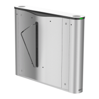
Shows the general wiring diagram for the flap barrier system.
Instructions on how to disassemble the pedestals, including lock holes.
Steps and notes for installing the pedestals, including clearance requirements.
Instructions for wiring the electric supply to the pedestal.
Explains how to connect the main lane board and sub lane board using interconnecting cables.
Shows how to connect the interconnecting cables between boards.
Details wiring for RS-485 and RS-232 interfaces, including connection examples.
Explains how the lane control board controls barrier status and third-party barriers.
Describes the wiring for alarm output signals.
Instructions for activating the device using the SADP tool.
Instructions for activating the device using client software.