Do you have a question about the HIKVISION DS-K3Y411 Series and is the answer not in the manual?
General information about the document's purpose and scope.
Lists trademarks and logos belonging to Hikvision and other owners.
Legal statement regarding product usage, liability, and warranties.
Information on personal data collection, storage, and processing principles.
Details compliance with FCC rules for digital devices.
States compliance with harmonized European standards for the product.
Covers crucial warnings, cautions, and instructions for safe operation.
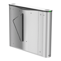
Provides a general overview of the flap barrier's purpose and applications.
Lists the key functionalities and capabilities of the flap barrier system.
Instructions on how to open pedestals using a key to access internal parts.
Steps and considerations for securely mounting pedestals to the installation surface.
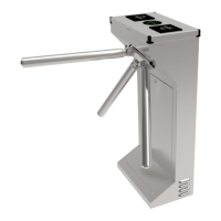
Describes the main components of the turnstile and their positions.
Details how to connect the power supply to the turnstile switch.
Explains how to connect main and sub lane boards using interconnecting cables.
Describes power supply connections for optional face recognition terminals.
Introduces the lane controllers and their role in managing components.
Identifies UART positions and terminals on control boards for communication.
Details specific UART numbers, terminals, and DIP switch settings.
Describes terminals on the main lane control board for various functions.
Describes terminals on the sub lane control board for various functions.
Explains how to connect various components using the BUS terminal.
Provides specific BUS terminal information for left and middle pedestals.
Describes the function of the access control board and its terminals.
Lists and describes the terminals available on the access control board.
Explains how to set device modes and communication via DIP switches.
Details the functions of DIP switches for UART communication modes.
Provides wiring instructions for RS-485 interfaces used for various readers.
Details wiring for RS-232 interfaces used for QR scanners, text screens, etc.
Explains how to control barrier status and third-party barriers.
Describes how to connect alarm outputs and change relay status.
Instructions for pairing remote controls (keyfobs) with the turnstile.
Steps to reset the device to its default settings and clear event logs.
Explains how to configure relay output modes for barrier and alarm functions.
Details how to set the barrier control relay to Normally Open (NO) or Normally Closed (NC).
Details how to set the alarm relay to Normally Open (NO) or Normally Closed (NC).
Guide on using the SADP tool to detect and activate devices on the LAN.
Instructions for activating devices through the client software interface.
| Brand | HIKVISION |
|---|---|
| Model | DS-K3Y411 Series |
| Category | Turnstiles |
| Language | English |