This document describes the Hikvision Tripod Turnstile, a sophisticated access control device designed for secure and efficient pedestrian flow management.
Function Description
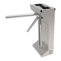
The Tripod Turnstile is an electric control mechanism integrated into building structures to form an access control system. It features a rotation unit with three tubular arms positioned at 120-degree intervals, ensuring one arm is always in a horizontal "barrier" position when at rest. Movement of the rotation unit is initiated by lightly pushing the arms. If an arm rotates beyond a set position, elastic potential energy drives the rotation unit to complete the full rotation.
The turnstile integrates electronic and mechanical rotation, functioning as an advanced access controller. It can be integrated with various card technologies such as RFIC, IC, and magnetic cards to meet diverse customer requirements. This makes it suitable for a wide range of applications, including conference rooms, parks, and railway stations.
Key functional features include:
- Standard Signal Input Port: Allows connection to most access control boards, fingerprint devices, scanners, and other equipment.
- Automatic Reset Function: If an authorized card is swiped but the person does not pass through within a set time, the card must be swiped again for entry.
- Card-reading Recording Function: Can be configured to record card reading events.
- Automatic Opening on Emergency: Opens automatically upon receiving an emergency fire signal.
- Anti-following: Prevents illegal passing by unauthorized individuals.
- High-light LED Indicator: Displays the current passing status (green for passage).
- Normal Open Control: Can be controlled via an external button or manual key unlock.
- Automatic Arm Drop: Arms automatically fall down in case of power failure.
- Anti-reversal Device: Prevents rotation of the rotary unit in the opposite direction once initial rotation has begun, ensuring one-way passage.
The electric control system comprises an access control device, control board, direction indicator, position sensor, solenoid, tamper, and power supply. The access control device (e.g., IC/ID card reader, fingerprint, face recognition, code reader) sends a delay signal to the turnstile board. Upon receiving this signal, the control board activates the solenoid to open, and the direction indicator turns green. When the arm is pushed 120 degrees, the position sensor sends a closing signal to the board, and the solenoid immediately locks. In the event of power loss, the arm will fall down.
Important Technical Specifications
| Item |
Description |
| House |
304 stainless steel |
| Reliability of the core |
3 million, no fault |
| Weight |
35 Kg |
| Arm length |
510 mm |
| Driving force of arms |
3 Kg |
| Direction of rotation |
Unidirectional/Bidirectional (controllable) |
| Indicator lamp |
Green means passage |
| Power supply for core |
AC100~220V |
| Operational voltage |
DC 24V ±5% |
| Voltage of indicator lamp |
DC12V ±5% (standard) |
| Working environment |
Indoor |
| Working temperature |
-30°C ~ 60°C |
| Humidity |
5% ~ 90% |
| Waterproof |
≥IP31 |
| Installation interfaces for card readers |
2 |
| Control interface |
Relay signal input |
| Time needed for opening |
0.2 seconds |
| Passing speed |
> 35 persons/min |
The product structure consists of a mechanical system and an electric control system. The mechanical system includes the arm, rotary unit, core, and housing. The core itself comprises a shock absorber, solenoid, toothed cam, position block, and position sensor.
Usage Features
Installation:
- Before installation, ensure the device functions correctly.
- Always cut off power before installation or maintenance.
- The product must be earthed, and an earth leakage breaker is required for the power supply.
- Buried PVC tubes should have a depth greater than 60mm and an exposed height above ground greater than 50mm, with the exit mouth bending back to prevent water ingress.
- Avoid casual changes to internal wiring.
- Ensure all lane doors are aligned during installation.
- Tighten mounting screws of the arm securely.
- For outdoor use, a canopy is recommended to protect the turnstile from sun and rain.
- Arm assembly involves powering on the turnstile, manually raising the drop arm down device to engage the circular solenoid, and then attaching the arm bars.
Debugging:
- Ensure proper grounding of the protective earth wire.
- Verify all wiring connections according to the provided diagram.
- Function test involves powering on, manually lifting the arm, and checking if the LED indicator shows green upon receiving an open signal.
Notices:
- Keep control buttons and remote controls out of reach of children.
- Do not use the turnstile during thunder and lightning conditions to prevent equipment damage.
- Children should be supervised when passing through the turnstile.
- Users should follow the proper order when swiping cards.
DIP Switch Settings:
The DIP switches allow configuration of automatic reset times (from 2 seconds to 13 seconds) and enable/disable the "swipe card memory" function. With memory function enabled, multiple valid card swipes can allow multiple people to pass (e.g., 5 swipes for 5 people). Without memory function, each swipe allows only one person to pass.
Maintenance Features
Regular inspection and cleaning are crucial for maintaining the components and checking for wear. The recommended inspection interval is based on an average of two million transits per year. This interval should be shortened in dusty environments (e.g., subway or light rail stations, recommended every 6 months).
General Maintenance:
- Always disconnect electrical power before inspecting the mechanism to avoid electric shock.
Component-Specific Maintenance (with power disconnected):
- Lock Arms and Solenoids: Grease the pins of the lock arms that slide on the solenoid shaft, and the solenoid shaft and spring. Do not grease the core of the solenoid. Check for free movement of the shaft/lock arm assembly.
- Oil Pressure of the Damper: Check for oil spills and ensure the spring exerts sufficient force, matching the damper's resistance. The spring force should be slightly more powerful than the damper.
- Upper Positioning Cam: Loosen the spring of the positioning lever. Check that the guide way in the cam is clean and free of excessive wear or metal powder. Check the guide pin of the positioning lever for excessive play. Ensure the magnetic strip is perfectly attached to the cam's edge. Refit and adjust the spring of the positioning lever.
- Tripod: Check the tightness of the three screws securing the base plate to the mechanism shaft.
- Emergency Drop Arm Device: Clean all dust from the arm detents, the arm drop lever, and the relative solenoid. Do not lubricate these parts.
- Cable and Connectors: Check that wire connectors are firmly attached, terminals are fully tightened, and wire insulation is in good condition with no exposed conductors.
Troubleshooting Tips:
- Reverse Arm Movement/Indicator: Exchange SW1 GND and SW2 GND terminals on the board if the arm moves in reverse or the indicator shows reverse.
- Indicator Not Working: Check indicator wiring and replace the indicator or board if damaged.
- Free for One Way: Remove one square solenoid.
- Arm Not Pushing After Swipe: Check 24V GND output for the square solenoid; replace the board or solenoid if necessary.
- Multiple People Passing After One Swipe: This can be due to the position sensor not being touched by the screw cap during rotation, the square solenoid not stretching smoothly, or control board damage. Solutions include adjusting the position sensor, adjusting/replacing the square solenoid, or replacing the control board.
- Arm Not Dropping on Power Failure: The drop arm device may be positioned too high, preventing the solenoid from attracting the plate. Adjust the drop arm device's height by hand and tighten screws.
- Arm Not Operating on Power On: Similar to the above, the drop arm device's height (too high or too low) can prevent proper engagement with the solenoid or arm lock. Adjust to a suitable position.
- Slow/Fast Rotating Speed: Adjust the shock absorber. If ineffective, check the machine core spring of the positioning lever for chucks or damage and replace the pedestal if needed.
- Arm Not Resetting: Check if the rotating part is scraping the box and reduce the buffer.