Hangzhou Hikvision Digital Technology CO.,Ltd. No.555 Qianmo Road, Binjiang District, Hangzhou 310052, China
D Series Door Staon
Diagram References
ENGLISH
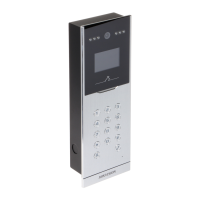
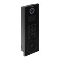
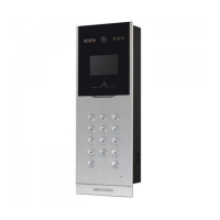
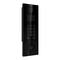
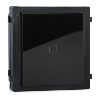
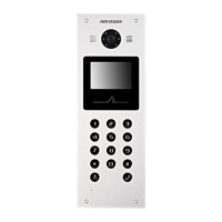
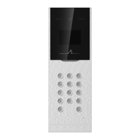
Appearance
1
IR Supplement Light
Camera
LCD Display Screen
1 2 3
4 5
6
Card Reading Area
Loudspeaker
Note: The appearance of the device vary according to different model. Refers to the actual device.
UD19916B
1
3
9Keypad 7 Call Buon 8 Call Center Buon Microphone 10 TAMPER
135
407.5
55
Unit : mm
DS-KD8023-E6
2
1
2
3
4
5
6
7
9
8
10
RES
GND
W1
W0
BZ
ERR
OK
TAMP
AO2-
AO2+
AO1-
AO1+
AIN4
AIN3
AIN2
AIN1
NO1
COM1
NC1
NO2
COM2
NC2
GND
RES
SEN1
BTN1
SEN2
BTN2
GND
485A+
485A-
GND
WIEGAND
12 VDC GND
LOCK1
LOCK2
ALARM OUT
ALARM IN
ALARM IN
LAN
RESERVED
POWER
RS485
Unit : mm
A
B
PA4 Screws
Hook C
PM3 Screw
POM2 Screw
1
2
3 4
Installaon
Before you begin:
Accessory
3
Terminal
2
1. Accessories that you need to prepare for installaon: gang box and mounng template.
2. Make sure the power supply meet the power requirements of the door staon (12 VDC, 1 A).
3. Make sure all the related equipment is power-off during the installaon.
4. Wire the cables before installaon.
The dimension of the gang box is: 407.5 mm(W) × 135 mm(H) × 55 mm(D).
The installaon hole should be larger than gang box. The suggested dimension of the installaon hole
is 408 mm(W) × 135.5 mm(H) × 55.5 mm(D).
Flush Mounng
1. Drill an installaon hole on the wall.
Note: The size of the hole should be larger than that of the gang box. The suggested size of hole is 408
mm(W) × 135.5 mm(H) × 55.5 mm(D).
2. Insert the gang box into the hole and fix it with 4 PA4 screws. Make sure the edges of the gang box
align to the wall and the hook A and hook B of the gang box hook onto the wall.Route the cables of the
door staon through the cable hole.
3. Insert the door staon into the gang box and then move the door staon downward to hook the lock
catches on the rear panel onto the hook C of the gang box. Fix the door staon with 2 PM3 screws.
4.Aer fixing the door staon onto the gang box, secure it by inserng the plate and insert 2 POM2
screws.
NC1/NC2: Door Lock Relay Output (NC)
NO1/NO2: Door Lock Relay Output (NO)
COM1/COM2: Common Interface
DC 12 V: Power Supply Input
AO1+/AO1- : Alarm Relay Output 1
AO2+/AO2- : Alarm Relay Output 2
AIN1/AIN2/AIN3/AIN4: Alarm Input
SEN1/SEN2: Door Contact Detecon Input/Door Contact
BTN1/BTN2: Door Contact Detecon Input/Exit Buon
GND: Grounding
485A-: RS-485 Communicaon Terminal
485A+: RS-485 Communicaon Terminal
TAMP: Wiegand Card Reader TAMPER
OK: Card Reader Indicator Output (Valid)
ERR: Card Reader Indicator Output (Invaild)
BZ: Card Reader Buzzer Output
W0: Data Input Interface Wiegand Card Reader
W1: Data Input Interface Wiegand Card Reader
RES: Reserved
Note: Wiring descripon refers to the User Manual.
Call from Main/Sub Door Staon
Call from Outer Door Staon
Configuraon4
Acvate Device
1. Power on the device to enter the acvaon page automacally.
2. Create a password and confirm it.
3. Press # to acvate the door staon.
Note:
Enter an 8 to 16 characters admin password.
When entering the password, taking the numeric key 2 as example, press the numeric key 2 once, the text
field shows “2”, and press it again in 1.5 s, the text field shows “a”, and press it again in 1.5 s, the text field
shows “b”, and so on.
Hold 0 to enter special characters.
Press # to confirm the password.
Press * to delete the password during entering.
You are required to acvate the device first by seng a strong password for it before you can use the device.
1
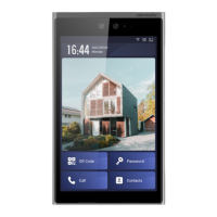
Call Resident
The door staon can work as main/sub door staon, and outer door staon, which correspond to different
calling resident modes respecvely.
Press number buon to enter the calling page.
Enter the room No. and press call buon again to call.
2
Call Center
3
Press number buon to enter the calling page.
Enter【Building No. + # + Unit No. + # + Room No.】 and press call buon to call resident.
Press number buon to enter the calling page.
Press center buon to call. Press * to cancel during calling management center.
Unlock by Entering Password
Unlock by Presenng Card
The device support unlock the door by presenng card, entering password, and fingerprint. Here
takes unlock by entering password and unlock by presenng card for example.
Note: You should create the password and add the card to the device first.
Common Password
Press number buon, enter【# + room No. + password + #】 to unlock the door.
Public Password
Note: Create the public password via iVMS-4200 Client Soware remotely first.
Press number buon, enter【# + public password + #】 to unlock the door.
Present the card on the card reading area to unlock the door.
Unlock Door
4
Refer to Video Intercom D Series Door Staon User Manual (scan the QR code) for details.