1
3
2
3
1
2
User Manual
4
1
I
II
2 3
4
a. b.
Hangzhou Hikvision Digital Technology CO.,Ltd. No.555 Qianmo Road, Binjiang District, Hangzhou 310052, China
xxxx
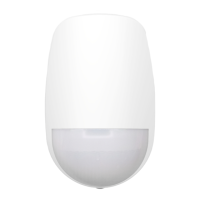
Device
Signal Strength Test
4
5
6
7
Magnet Test
I II
Start
Tilt Test
Start
3 min
Shock Test
Start
III
2. Línea de posicionamiento
1
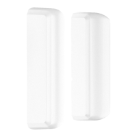
3. Piloto
7. Batería
1. Imán
5. Interruptor de alimentación4. Botón
anmanipulación
8. Sensor de golpes
Español
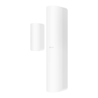
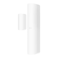
ASPECTO
6. Entradas externas
2
3
11 13
15 17
11 13
15 19
33 28
28 23
43 42
40 38
37 35
32 30
Compruebe que la posición de instalación sea la adecuada.
I. Prueba del imán
Tabla de rendimiento de detección de imanes
REGISTRO
PRUEBA
Sin distancia nominal
Con distancia nominal de
5 mm
Distancia en el aire Distancia en el aire
Extraer
Acercar
Extraer
Acercar
Extraer
Acercar
Extraer
Acercar
Extraer
Acercar
Evento
X+
X-
Y
Z+
Z-
Ejes de
operación
Sensibilidad Escenarios sugeridos
Alta Hormigón
Normal Madera
Baja Ventana
II. Prueba de impacto III. Prueba de inclinación
Puede establecer el ángulo de
inclinación (5-25º) en el soware de
cliente móvil.
Nota: La detección de inclinación solo
es aplicable a escenas horizontales o
vercales. Como norma de referencia,
el ángulo de inclinación es
perpendicular a la
dirección geocéntrica.
4
INSTALACIÓN
Manual de usuario
Escanee el código QR para obtener más información y ayuda
sobre el funcionamiento.
Especificación
Espacio de detección
En función de la tabla de rendimiento de detección
de imanes
Entradas externas 2
Detección de golpes Sí
Detección de inclinación Hasta 25º
Piloto led
Verde (MC), naranja (inclinación), rojo (impacto) y
azul (alarma)
Temperatura de
funcionamiento
-10 °C a 55 °C (14 °F a 131 °F)
-10 °C a 40 °C (14 °F a 104 °F) cerficado
Temperatura de
almacenamiento
-20 °C a 60 °C (-4 °F a 140 °F)
Humedad de
funcionamiento
10 % a 90 %
Dimensiones
(alto x ancho x fondo)
Sensor: 22,5 mm x 103 mm x 23,2 mm
Señal magnéca: 13 mm x 34,4 mm x 11,4 mm
Peso 60 g
Frecuencia de transmisión 433 MHz
Alcance de
radiofrecuencia
1 km (área abierta)
Batería 1 pila CR123A (incluida)
Vida úl de la batería
convencional
3 años
INSTALACIÓN
I. Revise la intensidad de la señal y alinee la línea de
posicionamiento.
II. Instale el detector
a. Con tornillo
b. Con burlete adhesivo de espuma
(no cumple con la normava EN)
Pase el cable a través de la perforación para cables en caso de
requerirse entradas externas.
Nota: No se recomienda la instalación con burlete adhesivo de espuma
si se habilita la detección de golpes.
8
Wireless Magnet Shock Detector
DS-PDMCK-EG2-WB
Quick Start Guide
Check if the installaon posion is properly.
INSTALLATION
English
APPEARANCE
1
4
ENROLLMENT
TEST
2
Specification
User Manual
3
Scan the QR code for more informaon and operaon help.
I. Check signal strength and align the posioning line.
II. Install the detector.
(oponal)route the cable through cable hole if external inputs required.
a. with screw b. with sponge tape (non EN compliant)
Detecon gap According to the magnet detecon performance table
LED indicator Green(MC), Orange(lt), Red(shock), Blue(alarm)
Operang temperature
-10 °C to 55 °C (14 °F to 131 °F)
-10 °C to 40 °C (14 °F to 104 °F) Cerfied
Storage temperature -20 °C to 60 °C (-4 °F to 140 °F)
Operang humidity 10% to 90%
Dimension (H × W × D)
Sensor: 22.5mm × 103mm × 23.2mm
Magnet: 13mm × 34.4mm × 11.4mm
Transmission frequency 433MHz
RF range 1 km (open area)
Baery CR123A × 1 (included)
Standard baery life 3 years
Note: Installaon with sponge tape is not recommended if shock detecon
enabled.
Note: The lt detecon is only applicable
to horizontal or vercal scenes. The lt
angle is perpendicular to the geocentric
direcon as the reference standard.
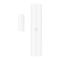
5. Power Switch 6. External Inputs
3. Indicator1. Magnet 4. Tamper Buon
7. Baery
2. Posioning line
8. Shock Sensor
FCC Informaon
Please take aenon that changes or modificaon not expressly approved
by the party responsible for compliance could void the user’s authority to operate
the equipment.
FCC compliance: This equipment has been tested and found to comply with the
limits for a Class B digital device, pursuant to part 15 of the FCC Rules. These limits
are designed to provide reasonable protecon against harmful interference in a
residenal installaon. This equipment generates, uses and can radiate radio
frequency energy and, if not installed and used in accordance with the instrucons,
may cause harmful interference to radio communicaons. However, there is no
guarantee that interference will not occur in a parcular installaon. If this
equipment does cause harmful interference to radio or television recepon, which
can be determined by turning the equipment off and on, the user is encouraged to
try to correct the interference by one or more of the following measures:
—Reorient or relocate the receiving antenna.
—Increase the separaon between the equipment and receiver.
—Connect the equipment into an outlet on a circuit different from that to which
the receiver is connected.
—Consult the dealer or an experienced radio/TV technician for help.
This equipment should be installed and operated with a minimum distance 20cm
between the radiator and your body.
FCC Condions
This device complies with part 15 of the FCC Rules. Operaon is subject to the
following two condions:
1. This device may not cause harmful interference.
2. This device must accept any interference received, including interference that
may cause undesired operaon
Magnet Detecon Performance Table
Without Nominal Distance With Nominal Distance 5mm
Distance in Air Distance in Air
Event
X+
X-
Y
Z+
Z-
Axes of
Operaon
Sensivity Suggested scenarios
II. Shock Test III. Tilt Test
You can set the lt angle (5° to 25°) in
the mobile client soware.
I. Magnet Test
4_KA3×25
5.5 ×24.5 mm
Z
X
Y
X
3. Indicador
7. Bateria
1. Magneto
5. Interruptor4. Botão de violação
8. Sensor de impacto
1
Português
APRESENTAÇÃO
2. Linha de posicionamento
6. Entradas externas
2
3
11 13
15 17
11 13
15 19
33 28
28 23
43 42
40 38
37 35
32 30
Verifique se a posição de instalação está correta.
I. Teste do magneto
Tabela de desempenho de detecção do magneto
REGISTRO
TESTE
Sem distância nominal
Com distância nominal de
5 mm
Distância no ar Distância no ar
Remover
Aproximar
Remover
Aproximar
Remover
Aproximar
Remover
Aproximar
Remover
Aproximar
Evento
X+
X-
Y
Z+
Z-
Eixos de
operação
Sensibilidade
Alta
Normal
Baixa
Cenários sugeridos
Concreto
Madeira
Janela
II. Teste de impacto III. Teste de inclinação
É possível definir o ângulo de
inclinação (5° a 25°) no soware
cliente móvel.
Observações: A detecção de inclinação
só se aplica a supercies horizontais ou
vercais. O ângulo de inclinação é
perpendicular à direção geocêntrica
como padrão de referência.
4
INSTALAÇÃO
Especificações
Manual do usuário
Leia o código QR para mais informações e ajuda na operação.
Detecção de folga
De acordo com a tabela de desempenho de detecção
do magneto
Entradas externas 2
Detecção de impacto Sim
Detecção de inclinação Até 25°
Indicador LED
Verde (MC), Laranja (inclinação), Vermelho (impacto),
Azul (alarme)
Temperatura de operação
-10 °C a 55 °C (14 °F a 131 °F)
-10 °C a 40 °C (14 °F a 104 °F) cerficada
Temperatura de
armazenamento
-20 °C a 60 °C (-4 °F a 140 °F)
Umidade de operação 10% a 90%
Dimensões (A × L × P)
Sensor: 22,5 mm × 103 mm × 23,2 mm
Magneto: 13 mm × 34,4 mm × 11,4 mm
Peso 60 g
Frequência de transmissão 433 MHz
Faixa de RF 1 km (área aberta)
Bateria CR123A × 1 (incluída)
Duração padrão da bateria 3 anos
INSTALAÇÃO
I. Verifique a força do sinal e alinhe a linha de posicionamento.
II. Instale o detector.
a. com parafuso
b. com fita dupla-face de espuma (em conformidade com a
norma EN)
(opcional) passe o cabo através do oricio para cabos se forem
necessárias entradas externas.
Observações: A instalação com fita dupla-face de espuma não é
recomendada se a detecção de impacto esver habilitada.