1
Disassembling the Detector
2
The Printed Circuit Board(PCB)
3
4 5
Installation Hints
6
The 18 m Lens
7
Resistor Wiring
8
Choose the Connection Type
9
Powering up
10
11
Dimension and Weight
(a) Lens (b) LED Light Pipe
(c) Lens Holder
(e) Nut
(d) PCB
(f) Casing Screw
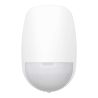
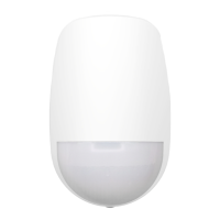
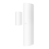
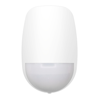
DS-PDP18-EG2
18 m Digital PIR Detector
(b) Tamper
Resisitor Headers
(d) Alarm
Resistor Headers
1K, 2K2,
4K7, 5K6, 8K2
(a) PIR Sensor
(c) Terminals
(e) Tamper
Spring
5K6, 4K7,
2K2, 1K
1
1
2
2
3
3
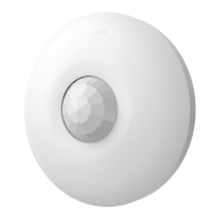
(1) Ceiling Bracket Fing
EN50131-2-2:2017
EN50131-1:2006+A1:2009+A2:2017
Security Grade (SG) 2
Environment Class (EC) II
(2) Wall Bracket Fing
(2) Single End of Line Wiring(1) Normally Closed (3) Double End of Line Wiring (4) Two Double End of Line Detectors to One Input
68 g
(2.4 oz)
1
2
3
4
The detector has two method for resistor wiring:
(1) Using headers to select the End of Line resistance (Control panel dependent) on the ALARM/TAMPER header pins.
(2) Select an resistance (Control panel dependent), and add the resistor to ALARM/TAMPER wiring ports of the detector.
Note: If EOL (End of Line) wiring is not used, leave the headers OFF. If the headers and the header pins does not
match, do not force the header, please select the method 2 to wire the resistor. Method 1 and method 2 should not
be used on the ALARM/TAMPER at the same me.
+
-
+
-
Technical Specification
85.9°
(a) Detecon Range
(b) Mounng Height
52 zones
4 planes
Mounng height range from 1.8 m to 2.4 m.
The recommended mounng height is 2.2 m.
=
=
(a) Alarm
Resistance
(b) Tamper
Resistance
1K,
2K2,
4K7,
5K6,
8K2
5K6,
4K7,
2K2,
1K
COPYRIGHT ©2019 Hangzhou Hikvision Digital Technology Co., Ltd.
ALL RIGHTS RESERVED.
Any and all informaon, including, among others, wordings, pictures,
graphs are the properes of Hangzhou Hikvision Digital Technology
Co., Ltd. or its subsidiaries (hereinaer referred to be “Hikvision”).
This user manual (hereinaer referred to be “the Manual”) cannot be
reproduced, changed, translated, or distributed, parally or wholly,
by any means, without the prior wrien permission of Hikvision.
Unless otherwise spulated, Hikvision does not make any warranes,
guarantees or representaons, express or implied, regarding to the
Manual.
About this Manual
This Manual is applicable to the 18 m Digital PIR Detector.
The Manual includes instrucons for using and managing the
product. Pictures, charts, images and all other informaon
hereinaer are for descripon and explanaon only. The informaon
contained in the Manual is subject to change, without noce, due to
firmware updates or other reasons. Please find the latest version in
the company website (hp://overseas.hikvision.com/en/).
Please use this user manual under the guidance of professionals.
Trademarks Acknowledgement and other Hikvision’s
trademarks and logos are the properes of Hikvision in various
jurisdicons. Other trademarks and logos menoned below are the
properes of their respecve owners.
This product and - if applicable - the supplied accessories too are marked with
"CE" and comply therefore with the applicable harmonized European
standards listed under the EMC Direcve 2014/30/EU, the LVD Direcve
2014/35/EU, the RoHS Direcve 2011/65/EU.
2012/19/EU (WEEE direcve): Products marked with this symbol cannot be
disposed of as unsorted municipal waste in the European Union. For proper
recycling, return this product to your local supplier upon the purchase of
equivalent new equipment, or dispose of it at designated collecon points.
For more informaon see: www.recyclethis.info
UD13284B
IC Information
CLASS B: CAN ICES-3 (B)/NMB-3(B)
Industry Canada ICES-003 Compliance
This device meets the CAN ICES-3 (B)/NMB-3(B) standards requirements.
This device complies with Industry Canada licence-exempt RSS standard(s). Operaon is
subject to the following two condions:
(1) this device may not cause interference, and
(2) this device must accept any interference, including interference that may cause
undesired operaon of the device.
Le présent appareil est conforme aux CNR d'Industrie Canada applicables aux appareils
radioexempts de licence. L'exploitaon est autorisée aux deux condions suivantes :
(1) l'appareil ne doit pas produire de brouillage, et
(2) l'ulisateur de l'appareil doit accepter tout brouillage radioélectrique subi, même si
le brouillage est suscepble d'en compromere le fonconnement.
Under Industry Canada regulaons, this radio transmier may only operate using an
antenna of a type and maximum (or lesser) gain approved for the transmier by Industry
Canada. To reduce potenal radio interference to other users, the antenna type and its
gain should be so chosen that the equivalent isotropically radiated power (e.i.r.p.) is not
more than that necessary for successful communicaon.
Conformément à la réglementaon d'Industrie Canada, le présent émeeur radio peut
fonconner avec une antenne d'un type et d'un gain maximal (ou inférieur) approuvé
pour l'émeeur par Industrie Canada. Dans le but de réduire les risques de brouillage
radioélectrique à l'intenon des autres ulisateurs, il faut choisir le type d'antenne et
son gain de sorte que la puissance isotrope rayonnée équivalente (p.i.r.e.) ne dépasse
pas l'intensité nécessaire à l'établissement d'une communicaon sasfaisante.
This equipment should be installed and operated with a minimum distance 20cm
between the radiator and your body.
Cet équipement doit être installé et ulisé à une distance minimale de 20 cm entre le
radiateur et votre corps.
FCC Informaon
Please take aenon that changes or modificaon not expressly approved by
the party responsible for compliance could void the user’s authority to operate
the equipment.
FCC compliance: This equipment has been tested and found to comply with the limits for
a Class B digital device, pursuant to part 15 of the FCC Rules. These limits are designed to
provide reasonable protecon against harmful interference in a residenal installaon.
This equipment generates, uses and can radiate radio frequency energy and, if not
installed and used in accordance with the instrucons, may cause harmful interference to
radio communicaons. However, there is no guarantee that interference will not occur in
a parcular installaon. If this equipment does cause harmful interference to radio or
television recepon, which can be determined by turning the equipment off and on, the
user is encouraged to try to correct the interference by one or more of the following
measures:
—Reorient or relocate the receiving antenna.
—Increase the separaon between the equipment and receiver.
—Connect the equipment into an outlet on a circuit different from that to which the
receiver is connected.
—Consult the dealer or an experienced radio/TV technician for help.
This equipment should be installed and operated with a minimum distance 20cm between
the radiator and your body.
FCC Condions
This device complies with part 15 of the FCC Rules. Operaon is subject to the following
two condions:
1. This device may not cause harmful interference.
2. This device must accept any interference received, including interference that may
cause undesired operaon
a. Alarm Control Panel a. Alarm Control Panel
b1. Detector 1 b2. Detector 2
b. Detector
b. Detector
a. Alarm Control Panel a. Alarm Control Panel
b. Detector
Aer powering on, the indicator flashes rapidly. Once the
detector self test is completed, the LED indicator will go
out unl the detector detects movement.
45.5 mm
65.4 mm
86.8 mm
Class B: This device is intended for mainly home use (Class B) and may be
used in all areas
B급 기기: 이 기기는 가정용(B급) 전자파적합기기로써 주로 가정에서
사용하는 것을 목적으로 하며, 모든 지역에서 사용할 수 있습니다.
The connecon shows
the example:
1. Normal: 1K
2. Alarm: 2K
3. Tamper: 0 K or infinite
The connecon shows
the example:
1. Normal: 1K
2. Alarm: Infinite
3. Tamper: 0 K
NOT READY READY
(g) Sensivity Sengs
LOW
AUTO (Default)
HIGH
(f) LED ON/OFF
LED ON
LED OFF
Screw Model
number
PA_3.5 ×25
4
Maximum detecon angle 85.9°
Maximum detecon distance 18 m
PIR sensivity High, Auto, Low
Tamper Front panel supports
Creep Zone Protecon Supported
An-insect interference Tight opcal cavity structure
Appearance LED Status indicator, blue,
Tamper interface 2
Alarm interface 2
Installaon height
,
Installaon mode Wall or Ceiling
Detecon 0.3 ~ 2 m/s
Operang voltage 9 to 16 VDC (Standard 12 VDC)
Current consumpon < 20 mA (12 VDC)
Operang temperature -10 °C to 40 °C (14 °F to 104 °F)
Weight 68 g (2.4 oz)
Dimension (H × W × D) 86.8 mm × 65.4 mm × 45.5 mm (3.4'' × 2.6'' × 1.8'')
ey Funco
Interface
Installaon
Others
Lens
Installation Method - Detector Backplane Installation
Installation Method - Bracket Installation
1K
10m 12m
14m
16m 18m
1m
2m 4m 6m 8m
10m 12m
14m
16m 18m
1m
2.4m
2m 4m 6m 8m
10m
12m
14m
16m
18m
1m
2m
4m
6m
8m
ALARMTAMPER
8K2
5K6
4K7
2K2
1K
1K
2K2
4K7
5K6
+-
ALARMTAMPER
EOLEOL
ALARMTAMPER
8K2
5K6
4K7
2K2
1K
1K
2K2
4K7
5K6
+-
ALARMTAMPER
EOLEOL
ALARMTAMPER
8K2
5K6
4K7
2K2
1K
1K
2K2
4K7
5K6
+-
ALARMTAMPER
EOLEOL
ALARMTAMPER
8K2
5K6
4K7
2K2
1K
1K
2K2
4K7
5K6
+-
ALARMTAMPER
EOLEOL
ZONE2
COM
ZONE1
COM
+
-
ALARMTAMPER
+-
8K2
5K6
4K7
2K2
1K
1K
2K2
4K7
5K6
ALARMTAMPER
EOLEOL
ALARMTAMPER
+-
8K2
5K6
4K7
2K2
1K
1K
2K2
4K7
5K6
ALARMTAMPER
EOLEOL
ALARMTAMPER +-
8K2
5K6
4K7
2K2
1K
1K
2K2
4K7
5K6
ALARMTAMPER
EOLEOL
ALARMTAMPER +-
8K2
5K6
4K7
2K2
1K
1K
2K2
4K7
5K6
ALARMTAMPER
EOLEOL
ALARMTAMPER +-
8K2
5K6
4K7
2K2
1K
1K
2K2
4K7
5K6
ALARMTAMPER
EOLEOL
ZONE2
COM
ZONE1
COM
+
-
ZONE2
COM
ZONE1
COM
+
-
ZONE2
COM
ZONE1
COM
+
-
1K