DS-PD1-MC-WWS
Wireless Magnec Contact
Diagram References
ENGLISH
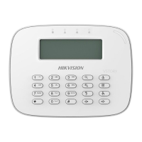
DS-19K00-Y/DS-PKFE-5
Wireless Keyfob
2
1 2
3
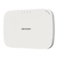
Control Panel x 1
Baery x 1
Magnec Door Contact x 1
Detector x 1
Keyfob x 1
Power Adapter x 1
Screw x 4
Quick Start Guide x1
2
1
4
4
2
5
2
6
2
2
2
3
Specification
21 22
23
COPYRIGHT ©2018 Hangzhou Hikvision Digital Technology Co., Ltd.
ALL RIGHTS RESERVED.
Any and all informaon, including, among others, wordings, pictures, graphs are the
properes of Hangzhou Hikvision Digital Technology Co., Ltd. or its subsidiaries
(hereinaer referred to be “Hikvision”). This user manual (hereinaer referred to be “the
Manual”) cannot be reproduced, changed, translated, or distributed, parally or wholly,
by any means, without the prior wrien permission of Hikvision. Unless otherwise
spulated, Hikvision does not make any warranes, guarantees or representaons,
express or implied, regarding to the Manual.
About this Manual
This Manual is applicable to the Axiom Security Control Panel Kit.
The Manual includes instrucons for using and managing the product. Pictures, charts,
images and all other informaon hereinaer are for descripon and explanaon only. The
informaon contained in the Manual is subject to change, without noce, due to firmware
updates or other reasons. Please find the latest version in the company website
(hp://overseas.hikvision.com/en/).
Please use this user manual under the guidance of professionals.
Trademarks Acknowledgement and other Hikvision’s trademarks and
logos are the properes of Hikvision in various jurisdicons. Other trademarks and logos
menoned below are the properes of their respecve owners.
Components
Product Informaon
3
1
2
3
4
1mm
This product and - if applicable - the supplied accessories too
are marked with "CE" and comply therefore with the applicable
harmonized European standards listed under the RE Direcve
2014/53/EU, the EMC Direcve 2014/30/EU, the LVD Direcve
2014/35/EU, the RoHS Direcve 2011/65/EU.
1
2 3
4
Indicator
Red: Press the Key Green: Successful Operaon
Away Arming
Indicator
Disarming
Clearing Alarm
Stay Arming
Panic Alarm(Hold for 2s)
Formang
1. Remove the baery.
2. Hold the Away Arming key of the keyfob, and reinstall the baery at
the same me to power the keyfob on . The formang is completed aer
the red LED flashes three mes.
1. Dig the groove to disassemble the device. Remove the front
and rear panel. Remove the insulating strip to power on the
device.
Note: Do not disassemble the device with sharps.
2. Assemble the front panel and rear panel.
Add Keyfob
You can add keyfob to the security control panel via the web client of the
control panel.
1. Click System → Keyfob to enter the Keyfob Management page.
2. Click Add and press any key on the keyfob.
3. Set the keyfob parameters.
4. Click OK.
Note: If the keyfob is required to be added to wired security control panel,
refer to the User Manual of Wired Security Control Panal for connecng
details.
Delete Keyfob
On the Keyfob Management page, you can delete a selected keyfob or
check mulple keyfobs and click Delete to delete in batch.
Note: You need to format the keyfob aer deleng to unregister it from a
control panel, which allows you to add the keyfob to another control
panel.
21 22 23
24 25 26
Appearance
1
Installaon
2
Registraon
3
CAUTION
RISK OF EXPLOSION IF BATTERY IS REPLACED BY
AN INCORRECT TYPE.
DISPOSE OF USED BATTERIES ACCORDING TO
THE INSTRUCTIONS
CHEMICAL BURNING DANGER
DO NOT SWALLOW THE BATTERY
KEEP NEW AND USED BATTERIES AWAY FROM
THE CHILDREN
Installaon Datum Line on the Sensor
Installaon Datum Line on the Magnec Sck
The sensor can detect the door or window opening. When the door or window is
open, an alarm will be triggered and it will be sent to the alarm center or mobile
client via security control panel.
Door Magnec Sensor Alarm: When the distance between the sensor and the
magnec sck is longer than 3 cm, an alarm will be triggered. The indicator will
flash once.
Tamper Alarm: When removing the sensor, an alarm will be triggered.
Power on the security control panel. Press the funcon buon once and then
trigger the detector. And you can add the detector accroding to the voice prompt.
The green LED of the detector will flash 8 mes aer being successfully added.
Note: The distance between the security control panel and the detector should be less than 50
cm.
Register the Detector Locally
Register the Detector via APP
1. Check Signal Strength
Enter the signal checking mode by operang on the control panel.Trigger the
detector.
Solid Green for 3 s - Strong Signal
Solid Red for 3 s - Weak Signal
1. Log in to the APP Store and input “Hik-Connect” to search the mobile client.
5. Log in the Hik-Connect and ap the icon “+” at the upper-right coner of the
Hik-Connect page to add the security control panel. You can scan the QR code on
the device rear panel or on the package box, or input the device serial No. manually
to add the device when the device is in the registraon mode.
6. Aer adding the security control panel, tap the arming status icon on the right of
the security control panel’s name to enter the Paron page.
2. Download and install Hik-Connect to your phone.
3. Aer installing, tap to run the client.
4. Power on the security control panel.
7. Tap the “+” icon on the Paron page to add the peripherals.
Indicator
Alarm Detecon:
Red LED flashes.
Display Signal Strength:
Under the signal strength checking mode:
Solid Green for 3 s - Strong Signal
Solid Red for 3 s - Weak Signal
TAMPER Buon
-Tampering Alarm: If the detector is disassembled, an alarm will be triggered.
-Formang: Remove the baery. Hold the TAMPER buon and power the
detector on at the same me. The red LED flashes 3 me when the formang
is completed.
Detector Installaon
2. Install the Detector
Paste the sponge tape on the rear side of the detector.
Paste the detector on the required place.
Note: To make the TAMPER work properly, the thickness of the sponge tape
should be no more than 1mm.
English
Diagram Reference
Specification
1
3
2
4
Appearance
1
Detector Power On
2
4
Detector Registraon
3
a
b
2. Assemble the front panel and rear panel by align ingthe Indicator groove on the
front panel with the Indicator light pipe on the rear panel.
1. Dig the groove to disassemble the device. Remove the front and rear panel.
Remove the insulang strip to power on the device.
Note: Do not disassemble the device with sharps.
3. Paste the sensor at the door or window’s edge. Make sure the
sensor is aligned with the door or window’s edge.
4. Paste the magnec sck at the door or window’s edge. Make sure the
magnec sck is aligned with the door or window’s edge.
Detector Formaed:
Red LED flashes once.
Transmission Distance 800m (Open Area)
Indicator LED 1(Dual-Color)
Power Supply Baery CR123A
℃
℃
Dimension(W*H*D) 25 x 84 x 20.99mm
Wireless
Materials and Environment
Modulaon 2GFSK
Transmission Distance 300m (Open Area)
Indicator LED
Red: Press the Key
Green: Successful Operaon
Power Supply Baery CR2032 3.0V
Temperature
Humidity 10%~90%
Dimension(W*H*D) 63.3*48.7*16.3mm
Wireless
Materials and Environment

 Loading...