DS-TMG033 Barrier Gate Radar User Manual
13
Figure 2-6 Hole Size
Step 2 Install gaskets.
Put gaskets for connector hole outside the waterproof connector.
Embed gaskets for threaded hole into threaded hole.
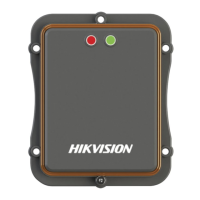
Step 3 Fix capture-trigger radar on rack and tighten screws.
Figure 2-7 Install Capture-Trigger Radar
2.3.3 Cabling
Connect radar plug to communication plug.
Connect “+12 V” to output positive terminal of 12 VDC power supply, while connect “GND” to
output negative terminal of power supply.
Connect capture –trigger radar J1-1 and J1-2 to camera trigger terminal.
 Loading...