Note:
Drill the cable hole, when adopting the ceiling outlet
to route the cable.
3. Attach the bracket to the ceiling and secure the
camera with supplied screws.
Figure 2-17 Fix the Camera to the Ceiling
Note:
The supplied screw package contains self-tapping
screws, and expansion bolts.
For cement ceiling, expansion bolts are required
to fix the camera. For wooden ceiling, self-
tapping screws are required.
4. Route the cables through the cable hole, or the side
opening.
5. Connect the corresponding power cord, and video
cable.
6. Power on the camera to check whether the image on
the monitor is gotten from the optimum angle. If not,
adjust the camera according to the figure below to get
an optimum angle.
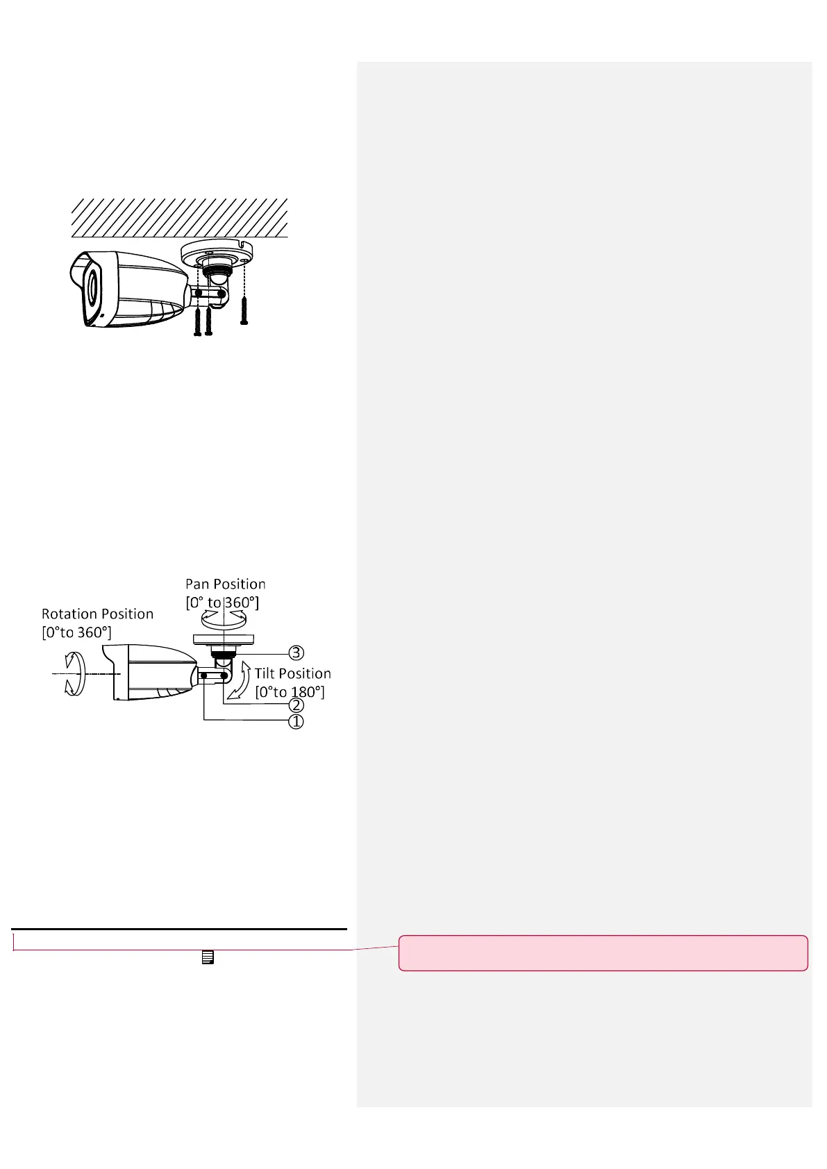
Figure 2-18 3-axis Adjustment
1). Loosen the No.3 screw to adjust the pan position
[0° to 360°]. Tighten the screw after completing
the adjustment.
2). Loosen the No.2 screw to adjust the tilt position
[0° to 180°]. Tighten the screw after completing
the adjustment.
3). Loosen the No.1 screw and rotate the camera [0°
to 360°]. Tighten the screw after completing the
adjustment.
3 Menu Description
Purpose:
Call the menu by clicking button on the PTZ Control
interface, or click Iris+.
Steps:
1. Connect the camera with the TVI DVR, and the
monitor, shown as the figure 3-1.
批注 [KL12]: 一定要点击 IRIS+ 才能进入菜单界面吗??
 Loading...