2.4.1 Easy-Connect System
The new system Easy-Connect, used in the central computers PROTEC4GSM and PROTEC8GSM,
it was projected to ease the installation and the maintenance of the system.
The circuit of the central is divided into two boards:
A-The board of connections / fuses.
B-The board of the console and CPU.
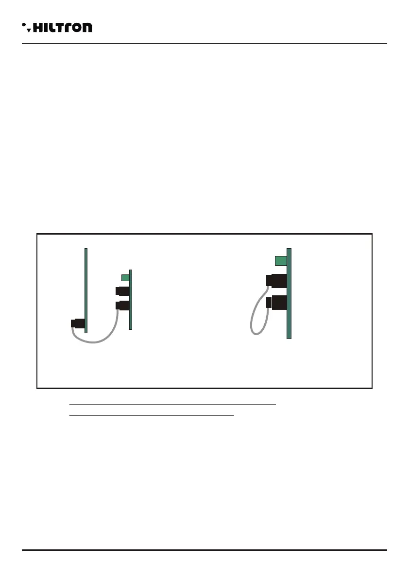
It is possible to cable the cables inside the central computer by removing the front panel
console/CPU completely, so that it can be achieved more space. Once you finish cabling, it is possible to
reassemble the front panel and connect it through the flexible multipolar cable rapidly.
Through the connecting cable, it is possible to activate the maintenance mode: disconnect the cable
from the console panel/CPU and insert it into the connector maintenance on the links tab; the red LED on
the board lights. In this mode, with the power supply connected to the network and/or the battery inserted,
the polarization of the external siren is maintained and stops to alert.
NOTES. The red led on the connection board
indicates the maintenance method.
NORMAL CONNECTION
B
A
A
WARNING!
In order to let operate the system correctly, the battery must always be connected.
2.4 Description of the board EASY-CONNECT
Once the connections are completed, insert the two conductors equipped with faston type connector from the
feeder to the battery, respecting the polarity of connection.
Red= [+] positive battery / Black= [-] negative battery
After connecting the battery of the central computer and the siren, you will turn on the system
through the selector connected to the power. The LED of the network on the panel of the central computer
stops flashing and it remains with a steady light to indicate the presence of the network tension. In order
to respect the regulations and for safety, you need to carry out and verify the connection to the earth
system to all the devices that need it.
Cx1
1 (Fusibile F1)
2 (Fusibile F2)
Cx1 Connector for internal transceiver DXR2 for devices series XR.
Notes: The transmitter DXR2 must be inserted with the components facing downwards.
Fuse 1A for outcoming services/ external power supply.
Fuse 1A for outcoming sirens.
6 output for internal sirens
7 Connection GND for sirens.
8 Output for external self-powered siren.
3-4 Output for the connection to LED V and R on additional control equipment devices PX,
SK, KB.
5 Input for command pulse about input/output from additional devices PX, SK, KB.
9-10 Connection for the new bus RS485 type DX bus for new devices series DX.
11 Connection GND for external power source.
12 Connection +12 for external power supply
13 Output for command/enabling connection for external devices.
14 Connection GND.
15 Input line 24h logic NC/ balanced
16 Connection GND
17/20 Line for the input of zone 1 4 logic NC / balanced.
21 Connection GND.
22-25 Line for the input zone 5 8 logic NC / balanced, ( PROTEC8GSM only).
JX1
JX2
JX1
JX2
JX1
JX2
-
JX1x1 JX1x2
JX1x3 JX1x4
JX1x5 JX1x6
JX1x7 JX1x8
JX1x9
JX1x10
JX1x11 JX1x12
JX1x13 JX1x14
JX1x15 JX1x16
JX1x17 JX1x18
JX1x19 JX1x20
JX1x21 JX1x22
JX1x23 JX1x24
JX1x25 JX1x26
JX1x27 JX1x28
JX1x29 JX1x30
JX2x1 JX2x2
JX2x3 JX2x4
JX2x5 JX2x6
JX2x7 JX2x8
JX2x9
JX2x10
JX2x11 JX2x12
JX2x13 JX2x14
JX2x15 JX2x16
JX2x17 JX2x18
JX2x19 JX2x20
JX2x21 JX2x22
JX2x23 JX2x24
JX2x25 JX2x26
JX2x27 JX2x28
JX2x29 JX2x30
SIR +12v
Manutenzione
Centrale
SIR
GND
S.A
V
R
KEY
A
B
-12V+
+INT GND 24H
1
2
3
4
5
6
7
8
9 10 11 12 13 14 15
16 17 18 19 20 21
GND Z1 Z2 Z3 Z4
CX1
GND
Z8
Z5 Z6 Z7
22 23 24 25
Installation
security
PROTEC4GSM - PROTEC8GSM - Installation guide and use
security
76
CONNECTION
MAINTENANCE
MODALITY
 Loading...