(APPENDIX II) CONTROL UNIT SCREENS | PAGE 74
IA: Start inhibited.
AE: External start.
CKG: Conrmation of genset contactor.
CKR: Conrmation of network contactor.
K-: Relay activation loading.
T: Test function.
F: Forced operation function.
JP1: EJP1 function.
JP2: EJP2 function.
The time remaining during the engine preheating and cooling process is dis-
played on the screen.
10.1.5 POWER AND ENERGY SCREEN
1. Measurements of actual power and cos phi per phase.
POWER: F P 1 . 0 0 L
3 0 k W F P 1 1 . 0 0 L
3 0 k V A F P 2 1 . 0 0 L
0 k V A R F P 3 1 . 0 0 L
FP: Total power factor.
FP1: Power factor phase 1.
FP2: Power factor phase 2.
FP3: Power factor phase 3.
2. Measurements of the total energy consumed in the Day, Month and Year.
ENERGY: P 3 0 k W h
D 1 0 K W h
M 1 0 0 M W h 1 7 : 5 6 : 2 3
A 1 0 0 0 M W h 4 / 1 2 / 0 6 L
D: Daily accumulated power.
M: Monthly accumulated power.
A: Annual accumulated power.
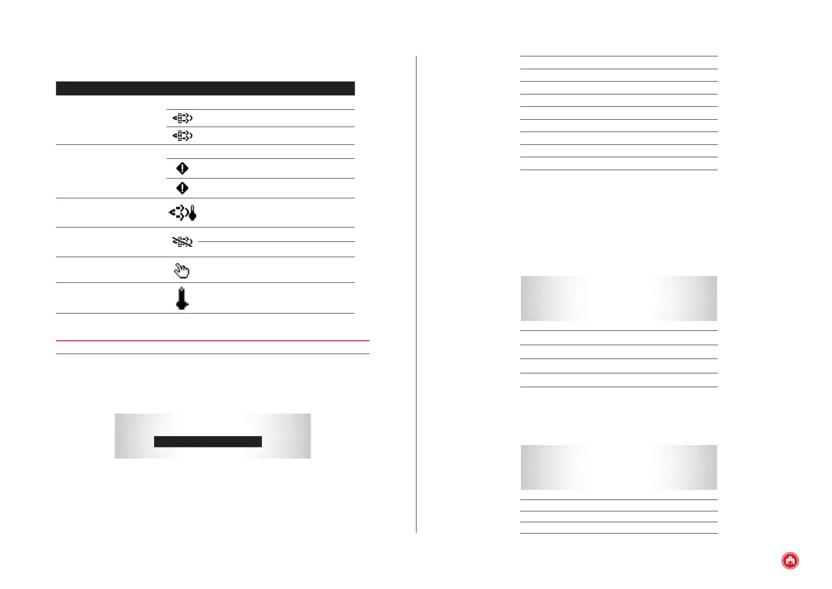
Tabla 1
Regeneration functionality icon table
DESCRIPCIÓN ICONO VALOR
DIESEL PARTICULATE FILTER
LAMP
SPN: 3697
OFF
ON
ON (blink).
FILTER PARTICULATE STATUS
SPN: 3701
Not required regeneration.
Required regeneration – Low level.
Required regeneration – High level (blink).
FILTER ACTIVE REGENERATION
STATUS
NORMAL SPN: 3700
Active regeneration.
REGENERATION
INHIBITED INTERLOCK SPN: 3702
INHIBITED SWITCH SPN: 3703
Inhibited regeneration by INTERLOCK.
Inhibited regeneration by switch (blink).
REGENERATION FORCED
SPN: 4175
Forced regeneration.
EXHAUST SYSTEM HIGH
TEMPERATURE
SPN: 3698
Exhaust system high temperature (blink).
NOTE
Regeneration icons only available for STAGE V/FINAL TIER 4 engines.
10.1.4 CONTROL UNIT STATUS SCREEN
1. Status of the programmable inputs
GENSET: STOPPED
I A
A E C K G C K R
K -
T F J P 1 J P 2
START INHIBITED
Fig.2
Status of the programmable inputs