7. Wiring Check
1
Check the measured values
and vectors.
2
Check the wiring judgment.
3
Press the [F2] (Next) key.
Check the wiring in the following cases.
• Measured values of the channels are
low
,
or active power Psum shows a
negative value.
• Displacement power factor DPFsum is
below 0.5.
• The vector position is outside the
PASS range.
Refer to Section 4.9 on the Instruction
Manual.
•
If (red) or (yellow) is displayed:
•
If all the items are judged to be (green):
•
The color was (yellow) but the wiring check
did not indicate any problems:
1. Move the cursor to the item in (red) or
(yellow) item.
2. Press the [ENTER] key.
3. Refer to the key points shown in the dialog to
correct the wiring.
8. Event Settings
1
Check the declared input
voltage.
2
Select the easy settings course.
3
Check the recording interval.
Changes can made in
“Step 9. Recording Settings”.
4
Press the [F2] (Next) key.
Easy settings course
Threshold values for events and recording interval will be automatically congured.
To make any change to the event settings
,
press the [SETUP] key after
completion of Quick Set to display the Event Settings screen.
Events that can be measured with the selected menu are displayed.
(Events are displayed with light color cannot be measured.)
Voltage events
This is used to investigate the cause
of power supply abnormalities such as
equipment malfunction.
Voltage components (swell
,
dip
,
interruption)
and frequency are monitored.
The recording interval will be set to 1 minute.
Inrush current
This is used to measure the inrush current.
Event thresholds for inrush current is set
to 200% of current RMS and the recording
interval to 1 minute.
Trend record only
This is used to record measured values over
an extended period of time.
All the event settings (effective only for
manual events
,
recording start events
,
and
recording stop events) are set to OFF and
recording interval is set to 10 minutes.
EN50160
This is used to measure in conformance to
the European Norm EN50160.
The recording interval is set to 10 minutes.
(The recording interval is xed to 10
minutes. Cannot be changed.)
Voltage events
1 min
Refer to Section 5.3 on the Instruction Manual.
9. Recording Settings
Tip
If the Save time is less than the measurement period
,
the following
methods can be used to increase the save time:
• Recording interval: Lengthened
• SD memory card: Delete unnecessary data
,
and format it.
(Exit the Quick Set and use the FILE screen.)
1
Congure the Recording start and Recording stop.
Interval: Recording will start at a well-dened time in accordance with the Recording
interval.
2
Press the [F2] (Next) key.
Manual
Interval
Refer to Section 5.2 on the Instruction Manual.
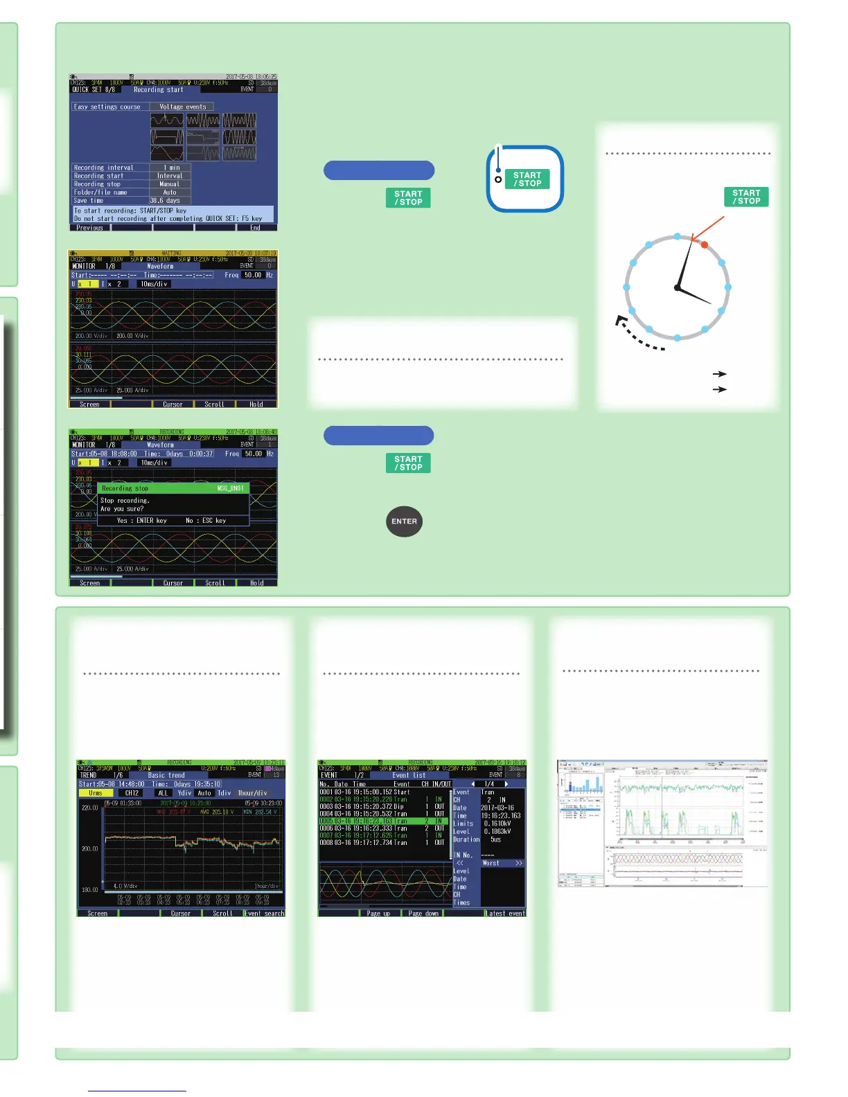
10. Checking Settings and Recording
1
Check the settings.
To make any changes to the settings
,
press the [F1] (Previous) key to return to
applicable screen.
Recording start
2
Press the key.
The instrument enters the standby state.
(START/STOP LED: Blinking)
The recording will start at the time set by the
interval*.
The instrument enters the recording state. (START/
STOP LED: On)
To start recording after setting the items
that are not listed in Quick Set.
Press the [F5] (End) key.
The settings congured up to this point will be
saved.
*: Interval
In case of Recording interval:
5 min
12
11
10
9
1
2
3
4
8
7
6
5
Recording
start
Recorded
Recorded
Recorded
Recorded
Recorded
Example 1:
4:02 4:05
Example 2:
12:43 12:45
Recording stop
3
Press the key.
The recording stop dialog will be displayed.
4
Press the key.
Recording will be stopped. (START/STOP LED: Off)
START/STOP LED
Refer to Chapter 7 on the Instruction Manual.
Fluctuations in measured
values during recording can be
monitored.
Press the [TREND] key to display the
TREND screen.
The measured items in the form of a
time series graph can be observed.
Event occurrence status during
recording can be monitored.
Press the [EVENT] key to display the
EVENT screen.
Event occurrence status can be
checked.
Recorded data can be post-
analyzed with a computer.
Data after completion of recording
can be analyzed with a computer
using the supplied PC application
software.
Refer to “8. Verifying the Trends
(Fluctuations) in Measured Values”
on the Instruction Manual for details.
Refer to “9. Checking Events” on the
Instruction Manual for details.
Functions:
• Observing time series data
,
event
data
,
and event waveform
• Observing statistics data
• Creating reports
Refer to “11. Analysis (with Computer)”
on the Instruction Manual for details.
www.GlobalTestSupply.com
Find Quality Products Online at: sales@GlobalTestSupply.com

 Loading...


