SERVICE & ROUTINE MAINTENANCE
CAUTION: maintenance and repairs must be carried out
by authorized personnel only. To prevent injury, always
remove the power cable from the power supply before
undertaking any work on the machine. Do not operate this
machine unless it is fully assembled and all guards are in
place. Use Hiretech genuine spare parts only.
General
1. Always make a list when first examining the machine, to
remind you of parts or action needed on completion of routine
maintenance.
2. The HTF-2 Floor Sander is subject to high speeds and
vibration, all screws should be fitted using a suitable thread
lock compound.
3. The HTF-2 Floor Sander needs no lubrication during routine
servicing.
4. Always ensure that the electrical supply is disconnected
before starting any routine servicing or repair.
5. Follow a regular schedule of routine maintenance to keep
your HTF-2 Floor Sander in good working.
Visual Inspection
1. To clean the machine and remove dust, use a vacuum cleaner
to avoid damage and prevent inhalation of dust.
2. Examine all external parts of the floor sander making sure
there is no damage. Check the condition of the Dust Brush
and Bumper around the base of the floor sander, both of
which should be undamaged and in good condition. Check
that the Handle Yoke unlocks and moves freely in its operating
position.
3. Examine the sanding pads. These should be undamaged and
in good condition. They should fit firmly to the fixing posts and
pivot slightly forward and back.
4. Examine the power cable for damage. If the outer insulation
shows the slightest of abrasions or the inner conductors are
exposed then the cable must be replaced. The cable must not
be repaired with tape or insulation sleeve.
5. Ensure all labels are sound, readable and secure.
6. Check that the rear wheels are sound and moving freely. If a
wheel is found to be loose or damaged then the floor sander
will not sand or handle properly. Check and reset the wheels
(see Setting the Wheels on page 8). Replace damaged
wheels.
7. Check the condition of the Dust Bag Frame making sure that
it hinges down in to its operating position and locks securely
when stowed.
Dust Control
1. Remove the handle and lay the floor sander on its face.
Remove the sanding pad if fitted and inspect the underside for
the build up of dust or pieces of abrasive. Clean as required.
2. Inspect the condition of the Dust Brush. The brush should be
replaced if damaged or badly worn.
Drive
1. The dive gears and drive belt do not require maintenance
under normal operating conditions.
Lubrication
1. The HTF-2 Floor Sander features sealed for life bearings
which do not require any lubrication. In the unlikely event that
a bearing has to be replaced use a Hiretech genuine spare
part only as the grease contained in the bearings is special.
A standard bearing is not suitable and may result in further
damage.
Care of Motor
1. The motor must be kept clean and free from grease and dust.
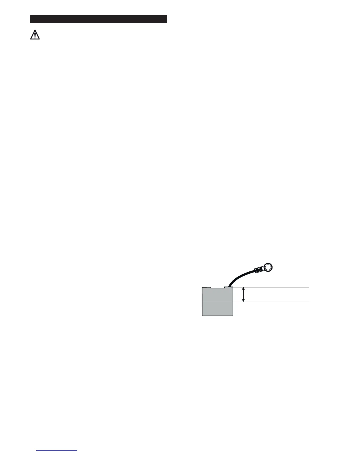
2. The motor brushes must be checked regularly. Replace
ALL FOUR motor brushes when any one brush has worn to
12mm (1/2”) or less in length. Brushes MUST slide freely in
the brush holders.
There is no need to remove or disconnect any internal leads
when changing the brushes, only the small braided shunt
(pigtail) connected to the motor brush is disconnected to
release the brush.
3. To replace the motor Brushes ;
i. Remove the four screws from the Motor Cover and lift the
cover off.
ii. Remove the four Spring Brushes and set to one side. The
springs are removed by pushing the spring tag in towards
the brush and lifting out.
iii. Using a cross recess screwdriver remove the four brush
shunt (pigtail) retaining screws and lock washers.
iv. Remove the four brushes.
v. Thoroughly clean the brush assembly and housing using
a soft brush and a suitable vacuum cleaner.
vi. Inspect the four brushes for damage or wear and if any
one brush is found to be damaged or worn to a length
of 12mm (1/2””) or less in length then replace all four
brushes. Always replace all four brushes together.
Motor Brush
vii. When replacing brushes ensure that each brush moves
freely in each brush holder and fit the brush with the shunt
(pigtail) in such a position as to allow free movement
throughout the brushes life. Ensure that each brush shunt is
connected securely with the screw and lock washer (two
spare screws and washers are provided with each pack
of brushes). The brush should be fitted so that the brush
shunt (pigtail) is at the bottom of the brush.
viii. Refit the brush springs by inserting into the holder with the
coil spring over the brush then push in until
the tag comes into contact with the holder, slide the tag
away from the brush and release. The brush spring will
clip into position. Check the springs and brushes for
correct alignment and free movement.
ix. Finally check that all leads and cables are clear of
moving parts and will not be trapped when refitting the
cover motor.
Minimum Brush Length
12mm ( /” )
1
2
7
© Hiretech

 Loading...