Do you have a question about the Hirschmann MAR1042 and is the answer not in the manual?
General precautions for safe operation and handling of the device with electricity.
Specifies authorized application cases and adherence to technical specifications for product use.
Details requirements for installing the device in a suitable environment for safety and performance.
Guidelines for opening the casing, handling connections, and avoiding hot surfaces during operation.
Requirements for qualified personnel and adherence to national/international safety standards for operation.
Procedure for grounding the device before connecting other cables.
Information on connecting shielded ground wires of twisted pair cables.
Detailed requirements for connecting the supply voltage, including isolation, fuses, and wire specifications.
Overview of MACH 1040 features, industrial automation suitability, and network capabilities.
Explains how to combine device characteristics to create specific product variants using a configurator.
Details different MACH 1040 models, their port configurations, and PoE support.
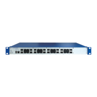
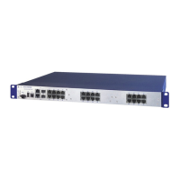
Describes the MAR1040 device variant with 16 Gigabit Ethernet ports and their front/back panel layout.
Details the MAR1042 variant, including 16 Gigabit ports and Power over Ethernet capability.
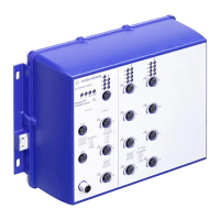
Covers MAR1040 variants with all cable outlets on the back panel, plus a front diagnostic port.
Describes MAR1142 variants with rear ports, PoE, and front diagnostic port features.
Explains Power over Ethernet (PoE) support for MAR1042/MAR1142, including IEEE 802.3af compliance.
Details the 16 combo ports supporting up to 1000 Mbit/s via RJ45 or SFP transceivers.
Describes the RJ45 socket port for 10/100/1000 Mbit/s connections, including PoE support.
Explains the SFP slot port for 100/1000 Mbit/s fiber optic connections according to IEEE 802.3 standards.
Provides pin assignment details for RJ45 and M12 connectors for different speeds and PoE.
Details the LED indicators for device and port status, and their meanings.
Explains the meaning of P, RM, R1, and R2 LEDs for indicating device status and power supply conditions.
Describes the function of port LEDs for link status, data activity, and boot procedure display.
Overview of interfaces for device management and configuration.
Details the RJ11 V.24 serial interface for CLI connection and system monitoring.
Explains the USB interface for connecting the AutoConfiguration Adapter for data and software management.
Describes the potential-free relay contact for remote diagnosis and external device control.
Instructions to verify all items are present and check for transport damage.
Step-by-step guide for installing an optional SFP transceiver into its slot.
Procedures for connecting power supply units and signal contacts using terminal blocks.
Detailed instructions and warnings for connecting the DC and AC supply voltage to the device.
Guidelines for connecting signal contact wires, including torque and wire specifications.
Covers mounting the device in cabinets or vertically, and proper grounding procedures.
Instructions for installing the device in a 19" switch cabinet using sliding or mounting rails.
Procedures for mounting the device vertically on a wall, including fire hazard warnings.
Explains how to ground the device using the dedicated grounding screw on the back.
Simple instruction on how to start up the device by connecting the supply voltage.
Guidance on connecting twisted pair and optical fiber cables to the device ports.
Recommendations for connecting twisted pair cables in environments with electrical interference.
Instructions for connecting optical fiber cables, ensuring correct port compatibility.
Steps to disconnect cables, power, and grounding before detaching the device.
Instructions for safely pulling out an SFP transceiver from its slot.
Detailed technical specifications for the device, covering electrical, physical, and environmental parameters.
EMC immunity test levels for IEC/EN 61850-3 standard, covering discharges, fields, and surges.
EMC immunity test levels for IEEE 1613 standard, focusing on discharges, fields, and transients.
Information on emission standards like EN 55022 and FCC 47 CFR Part 15.
Details on environmental tests including cold, dry heat, humidity, vibration, and shock resistance.
Defines the maximum length for twisted pair segments and provides data for fiber ports.
Power details for MAR1040/MAR1140 models, including SFP and TP port contributions.
Power details for MAR1042/MAR1142 models, including PoE capabilities and PD connection impact.
Catalog of Gigabit Ethernet SFP transceivers with associated order numbers for various fiber types.
Catalog of bidirectional SFP transceivers, including bundled types, with order numbers.
References standards for EMC, safety, industrial control, and railway applications.
References IEEE standards related to Ethernet, switching, and VLANs.
Provides contact information for technical questions and support across different regions.
Information on consulting, training, and support services offered by the Competence Center.
| Brand | Hirschmann |
|---|---|
| Model | MAR1042 |
| Category | Switch |
| Language | English |