Do you have a question about the Hirschmann MACH1040 and is the answer not in the manual?
Explains the meaning of various warning and informational symbols used in the manual.
Covers safe handling, operation, and maintenance of the device.
Specifies conditions and limitations for product use.
Guidelines for selecting an appropriate and safe installation location.
Importance and methods for relieving mechanical stress on cables.
Rules for authorized personnel accessing the device casing.
Defines the necessary qualifications for personnel working with the device.
Emphasizes adherence to applicable electrical safety regulations.
Procedures and requirements for properly grounding the device.
Information on connecting the shielded ground wire for twisted pair cables.
Detailed requirements for connecting the device's power supply.
States compliance with FCC Part 15 rules for Class A digital devices.
Contact details for Belden in the USA.
Guidelines for proper disposal of the device as electronic waste.
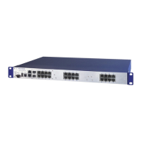
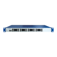
Overview of the device's features, variants, and management options.
How product designations are formed by combining characteristics.
Details on MACH1040, MAR1140, MAR1042, MAR1142 variants and PoE support.
Information about the 16 combo ports for transmission speeds up to 1000 Mbit/s.
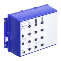
Explanation of LEDs and their meanings for device and port status.
Details on V.24 and USB interfaces for device management and configuration.
Description of the potential-free relay contact for remote diagnosis and control.
Steps to verify all items are included and check for transport damage.
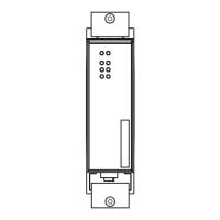
Procedure for installing SFP transceivers, including prerequisites and sequence.
Instructions for connecting supply voltage and signal contacts using terminal blocks.
Guidelines for mounting the device in a switch cabinet or on a wall and proper grounding.
Simple instruction on starting the device by connecting the supply voltage.
Recommendations for connecting twisted pair and optical fiber data cables.
Guide to changing the default password for secure initial access.
Steps to safely disconnect and detach the device from its mounting.
Procedure for removing an SFP transceiver from its slot.
Comprehensive technical specifications for dimensions, weight, power, and contacts.
Visual representations of device dimensions for mounting purposes.
Details on electromagnetic compatibility and immunity test levels according to standards.
Specifies line lengths for transceivers based on fiber type and attenuation.
Lists the technical standards and certifications the device complies with.
| Switching Technology | Store-and-Forward |
|---|---|
| Device Type | Managed Switch |
| Ports (Example Configuration) | 4 x 10/100/1000Base-T |
| Power Supply | 24V DC or 110-240V AC |
| Operating Temperature | -40°C to +70°C |
| Operating Temperature (Alternative) | -40 to +70 °C |
| Mounting | DIN Rail |
| Input Voltage | 24/36/48 V DC (9.6 ... 60 V DC) or 60/120/250 V DC (48 ... 300 V DC) or 110/230 V AC (85 ... 264 V AC) |
| MAC Address Table Size | 8, 000 entries |
| MAC Address Table (Alternative) | 8, 000 entries |
| Redundancy | RSTP, MRP |
| Security | 802.1X, ACL |
| Management | Web-based, SNMP |
| Jumbo Frame Support | Up to 9216 bytes |
| Power Supply (Alternative) | 24V DC or 110-240V AC |