Do you have a question about the Hirschmann MACH1000 Series and is the answer not in the manual?
Overview of the device's capabilities, variants, and connectivity options.
Details product designations and combinations for MACH1000 variants.
Illustrates exemplary port numbering sequence for all device variants.
Details front panel elements and port configurations for dual Gigabit models.
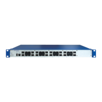
Details front panel elements and port configurations for quad Gigabit SFP models.
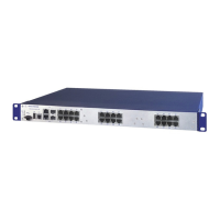
Details front panel ports for models with mixed SFP and RJ45 Gigabit interfaces.
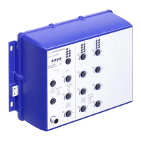
Describes front panel features and ports for Power over Ethernet (PoE) enabled models.
Illustrates and describes the rear panel layout and port connectivity.
Details power supply connections for terminal types, including DC/AC voltage.
Explains Power over Ethernet capabilities and conditions according to IEEE 802.3af.
Describes the RJ45 port, its speed support, and autonegotiation features.
Details the RJ45 port for 10/100 Mbit/s speeds and pin assignments.
Describes the SFP slot for 1000 Mbit/s fiber optic connections.
Details fiber optic ports (ST, LC, DSC, MTRJ, SFP) for 100 Mbit/s.
Describes the ST socket for 10 Mbit/s fiber optic connections.
Provides pinout details for RJ45 and M12 connectors for data and PoE.
Explains the meaning of LEDs indicating the device's operational status.
Details the meaning of port status LEDs (Link/Data, Stand-by, disabled).
Describes the serial V.24 interface for external management and its settings.
Details the USB interface for AutoConfiguration Adapter and software loading.
Explains the potential-free relay contact for remote diagnosis and event signaling.
Verify received items are complete and undamaged.
Instructions for installing SFP transceivers with a visual sequence.
Guide to connecting power supply and signal contacts.
Connects DC voltage supply to terminal blocks (C, G) with safety warnings.
Connects DC/AC voltage supply to plugged terminals (L, M) with safety notes.
Details connecting the signal contact lines for plugged and terminal connections.
General instructions for installing and grounding the device safely.
Guidance on mounting the device in a 19-inch switch cabinet using rails.
Instructions for vertically mounting the device, emphasizing fire enclosure use.
Details the grounding procedure using the rear grounding screw.
Basic steps to start up the device after connecting the supply voltage.
Recommendations for connecting data cables, considering interference.
Connects data cables to Twisted Pair ports according to requirements.
Connects data cables to Optical Fiber ports ensuring correct type matching.
Procedure for safely disconnecting and detaching the device.
Step-by-step guide for removing SFP transceivers from their slots.
| Series | MACH1000 |
|---|---|
| Type | Industrial Ethernet Switch |
| Switching Technology | Store-and-Forward |
| Power Supply | Redundant power supply option available |
| Power Consumption | Varies depending on model |
| Operating Temperature | -40°C to +70°C |
| Mounting | DIN-rail or wall mounting |
| Management | Web-based, SNMP, CLI |
| Protection Class | IP30 |
| Approvals | CE, FCC, ATEX |
| Power over Ethernet (PoE) | Available on select models |
| Redundancy | MRP, PRP, HSR |
| Layer | Layer 2 |
| Dimensions | Varies depending on model |
| Weight | Varies depending on model |