26
Installation MACH1000
Release
06
03/2021
1.3.6 Views MACH1000, ports on the back
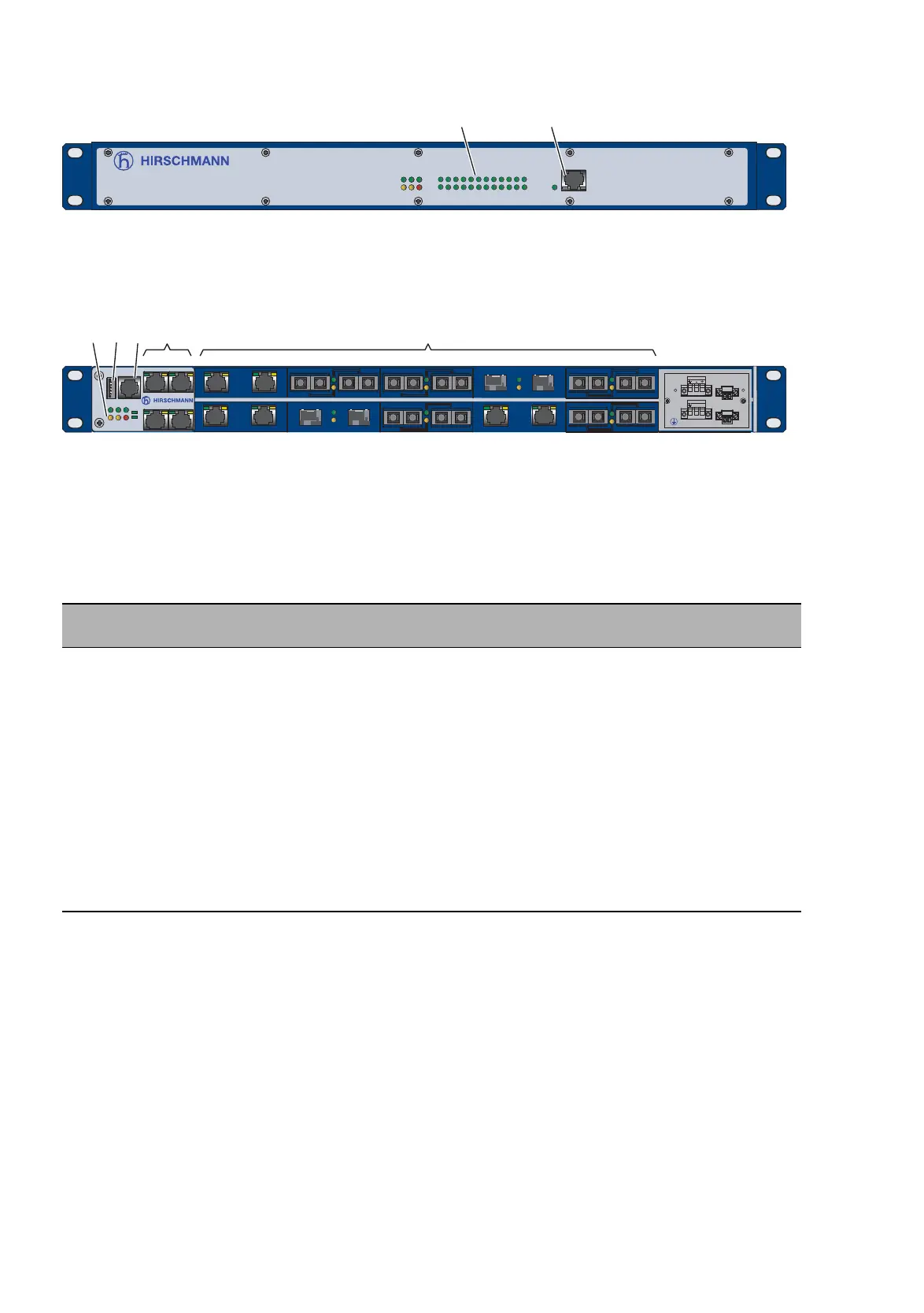
Figure 6: Front panel:
1 - LED display elements
2 - Diagnosis port
Figure 7: Rear panel:
1 - LED display elements
2 - USB interface
3 - V.24 connection for external management
4 - See following table, column 1
5 - See following table, column 2
The device variants of the MACH1000 with ports on the rear panel
have the following characteristics:
The display LEDs are on the front of the device. There are up to 4 LEDs
for displaying the status of the Gigabit Ethernet ports and up to 21 LEDs
for displaying the status of the Fast Ethernet ports, as well as 6 LEDs for
displaying the device status.
The supply voltage connection and the ports are on the back of the
device. The device allows you to connect a maximum of 20 Fast Ethernet
ports as well as an additional Fast Ethernet port on the front of the device
that you can use for diagnosis purposes.
Gigabit Ethernet
Up to 4 × GE ports
Fast Ethernet
FE ports 1 ... 20, connection as required
1000 Mbit/s
Fiber optic, SFP slots
And / or:
10/100/1000 Mbit/s
Twisted pair, RJ45 connections
99:
TT:
MM:
JJ:
NN:
VV:
UU:
LL:
GG:
ZZ:
RR:
FF:
Module position empty
2 × Twisted pair TX, RJ45, 10/100 Mbit/s
2 × Multimode FX DSC, 100 Mbit/s
2 × Multimode FX MTRJ, 100 Mbit/s
2 × Multimode FX ST, 100 Mbit/s
2 × Singlemode FX DSC, 100 Mbit/s
2 × Singlemode FX ST, 100 Mbit/s
2 × Singlemode Long Haul FX DSC, 100 Mbit/s
2 × Singlemode Long Haul FX DSC, 124.27 mi (200 km),
100 Mbit/s
2 × SFP slot, 100 Mbit/s
2 × Twisted pair TX, RJ45, 10/100 Mbit/s
2 × Multimode FL ST, 10 Mbit/s
P
StandByRM
FAULT
R1
R2
ETHERNET Service Port
1
3
5
7
9
11
13
15
17
19
21
23
2
4
6
8
10
12
14
16
18
20
22
24
MACH 1000
12
USB
V.24
MACH 1000
2
1
P
StandByRM
FAULT
R1
R2
25
26
23
24
22
USB
V.24
P
StandByRM
FAULT
R1
R2
2
1
MACH 1000
21
12
453
-/N +/L
 Loading...