Installation MACH1040
Release
05
03/2021
35
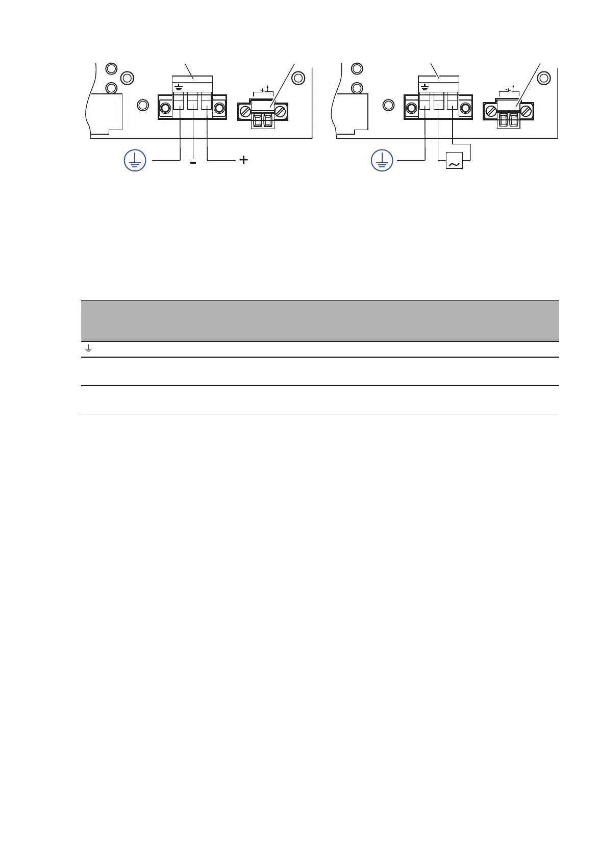
Figure 4: Power supply unit supply voltage characteristic value M (see on page 45
“General technical data”):
AC voltage (right figure) or DC voltage (left figure)
Connecting
1 - Supply voltage
2 - Signal contact
For every supply voltage to be connected, perform the following steps:
Verify the required conditions for connecting the voltage supply.
See “Supply voltage” on page 9.
Remove the terminal connector from the device.
Connect the protective conductor with the clamp.
Connect the wires according to the pin assignment on the device with the
clamps.
Mount the terminal block on the device using screws.
2.3.2 Wiring the signal contact
Relevant for North America:
The torque for tightening the terminal block for the signal contact on the
device is 3 lb-in (0.34 Nm).
Note: Use copper wire with cross-section AWG 20 to AWG 12 (0.5 mm
2
to
3.0 mm
2
) and stripping length12 mm.
Connection Power supply
characteristic value L
Power supply
characteristic value M -
VDC
Power supply
characteristic value M -
VAC
, pin 1 Protective conductor Protective conductor Protective conductor
-/N, pin 2 Minus terminal of the
supply voltage
Minus terminal of the
supply voltage
Neutral conductor
+/L, pin 3 Plus terminal of the
supply voltage
Plus terminal of the supply
voltage
Line conductor
Table 10: Pin assignment of terminal block for voltage supply
1 2
Relay
-/N +/L-/N +/L
G
Relay
1 2