Installation MSP30/32/40/42 and MSM20/22/24/40/42/46/50
Release
12
06/2018
49
On the front of the device there is an LED display that informs you about the
status of the interface.
1.9.3 USB interface
Note: Applies to approval DNV GL:
Note that the USB interface of the MSP30/32/40/42 is for service purposes
only. Do not connect any USB adapter during normal operation.
The USB interface allows you to connect the AutoConfiguration Adapter
ACA21/22 storage medium. This is used for saving/loading the configuration
data and diagnostic information, and for loading the software.
The device supports the ACA21/ACA22 starting with the software version
3.0.
The USB interface has the following properties:
Supplies current of max. 500 mA
Voltage not potential-separated
Connectors: type A
Supports the USB master mode
Supports USB 2.0
Note: For information about the position on the device see “View from below”
on page 28.
1.10 Input/output interfaces
1.10.1 Signal contact
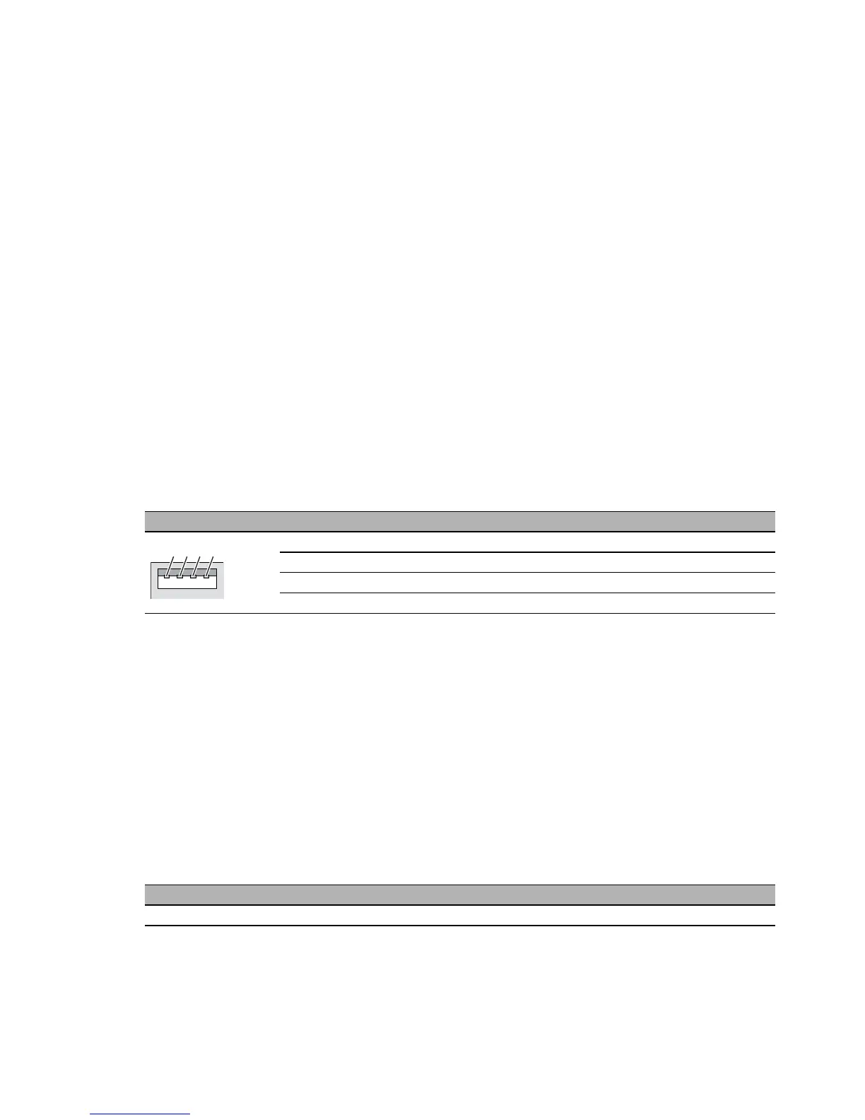
Figure Pin Operation
1 VCC (VBus)
2 − Data
3 + Data
4 Ground (GND)
Table 36: Pin assignment of the USB interface
Figure Pin Function
Connection for the power supply including signal contact P1
Table 37: Pin assignment of the 4-pin terminal block for the connection of the signal
contact
1
2
4
3