52
Installation OZD Profi 12M ...
Release
01
07/2017
4.10 Connecting the analog voltage outputs
(optional)
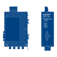
Figure 8: Analog voltage outputs – connections for 3-pin terminal block
The device has two analog voltage outputs, Ua1 and Ua2. These voltage
outputs are connected using a 8-pin screw terminal on top of the repeater.
The screw terminal is suitable for cable leads that have a cross section
between 0.2 - 2.5 mm
2
.
The analog voltage outputs supply a short-circuit-proof output voltage
dependent on the optical power input at port 2 or port 3, for diagnosis
purposes and, for example, for preventative maintenance, in the range from
0 - 5 V (each with reference to “GND” of the 8-pin terminal block). The analog
voltage outputs are electrically connected to the front panel/function ground.
The measuring voltage can be determined by a standard volt meter
(ungrounded, high-impedance) . This allows the incoming optical power to be
documented , e.g. for later measurements (aging, damage), a pass/fail
examination to be performed (threshold value), wiring to be carried out on
input terminals of a Profibus I/O module, thereby making the control system
available. As with other process variables, it is possible to define warning
thresholds there and use them for preventative maintenance.
 Loading...