4.5 Installation
25
4 Setting Up
Version 2.4 04/07
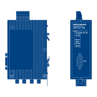
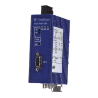
4.5.5 Connecting the power supply
The terminal block can be removed from the device to
connect the lines.
䊳
The module should only be supplied with a regulated
safety extra-low voltage in accordance with
IEC 950/EN 60 950/VDE 0805 with a maximum of
+32 VDC (typical +24 VDC). The power source must
comply with the regulations of the NEC, Class 2 in
accordance with UL/CSA approval.
It can be fed in using the 5-pin terminal block on the
top of the module.
䊳
To increase operational safety, the module can be
redundantly supplied via the terminals L2+/+24 VDC*
and M/ .
In the event of a failure of the regular power supply,
the module switches automatically to the redundant
power supply. Load distribution between the individual
alternative supply sources does not take place.
The signaling contact does not signal the failure of
a single 24 V infeed. Both of the infeeds and the
signaling contact must be connected to an input
module for monitoring to take place.
Clips on the terminal block ensure that it is securely
attached to the device, and simultaneously provide
polarity reversal protection.
4.5.6 Connecting the signaling contact
lines
The terminal block can be removed from the device to
connect the lines.
A relay with unconnected contacts as signaling contacts
is fitted to the 5-pin terminal block on the top of the
module. This signals faults and interference in the net-
work and modules. The contact is open if a fault occurs.
This also signals a total loss of power at the module.
Refer to Chapter 5.1 ”LED indicators“ p. 27 for more
details about malfunctions which are signaled by the
signaling contact.
Signaling contact limit values:
– maximum switching voltage 60 VDC; 42 VAC
– maximum switching current 1.0 A
The voltage connected to the relay must be regulated
safety extra-low voltage in accordance with
IEC 950/EN 60 950/ VDE 0805 and must comply with
the regulations of the NEC, Class 2 in accordance with
UL/CSA approval.