5.2 Troubleshooting
29
5 LED Indicators and Troubleshooting
Version 2.4 04/07
This chapter helps you to localize faults after they have
been indicated (by LEDs or signal contacts).
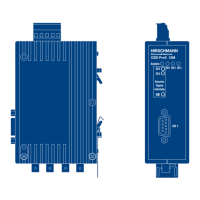
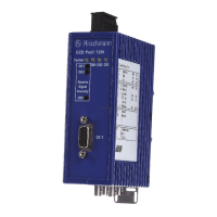
Please also refer to the description of the LED indicators
in 5.1, p. 27.
5.2 Troubleshooting
Fault indicated on the system LED
See description of the LED indicators in 5.1, p. 27.
Fault indicated on CH1
Check the following:
䊳
the DIL switch S0 is in Position 1 if the OZD Profi
connected to the electrical star segment of a star
topology (see Chap. 3.2 ”Star topology“, p. 12).
䊳
the fault is still displayed after removal of the RS485
connector.
Still displayed: Device is defective*.
Replace the OZD Profi.
No longer displayed: The fault lies in the RS485 bus
segment.
Check
– all RS485 connectors as described in 4.5.4
”Connecting the electrical RS 485 bus lines“,
p. 24
– the structure and shielding of the RS485 bus
segment
– the RS485 bus segment using a PROFIBUS bus
monitor
– the configuration of all bus subscribers.
* This is not the case if the monomaster of a PROFI-
BUS network is connected to the RS485 bus segment
which is to be examined. Replace the OZD Profi con-
cerned with another OZD Profi from the network, and
then carry out the test described above.
If the OZD Profi still malfunctions when connected
elsewhere, the device is defective. Replace the OZD
Profi.
If the OZD Profi does not malfunction elsewhere, the
fault lies in the RS485 bus segment.
Carry out the measures described above.
Fault indicated on CH2 / CH3
1. Check the following:
䊳
optically only modules of the same type are con-
nected together (see 3, ”Network topologies“, p. 9)
䊳
the optical fiber has been approved for the module
type being used, and that it does not exceed the per-
mitted length (see Table 1, p. 6)
䊳
the optical ports, which are connected via optical
fibers, have been set to the same operating mode
(see 4.4, ”Setting compatibility, operating mode and
transmitting power“, p. 17)
䊳
the settings given in 4.5.2, ”Connecting the optical
lines“ (p. 22) have been observed when connecting
and laying the optical bus lines.
2. Define the optical receiving level (see 4.5.7 ”Defining
the receiving level of the optical ports“, p. 26 and
8.7 ”Measuring sockets“, p. 37):
– Level is in the range ”Function is not guaranteed“.
䊳
Check the optical fiber absorption using an opti-
cal level measuring device.
too high: replace the optical fiber
in valid one of the two OZD Profi of the disturbed
range: optical fiber segments is defective.
First replace the other OZD Profi of the
disturbed optical fiber segments (i.e.
the OZD Profi, which supplies the send
signal for the measurement described
above). If the fault still persists, replace
the other OZD Profi instead.
– Level is in the range ”Optical system reserves
reduced“ or ”Normal mode“.
䊳
As described above, check the optical receiving
level of the other OZD Profi in the disturbed optical
fiber segment at the appropriate port.