4
1. Functional description
The ports of an RS2-4R represent a terminal
connection for the connected LAN segment.
You can connect single devices or complete
network segments.
1.1 FRAME SWITCHING FUNCTIONS
The RS2-4R supports the following frame
switching functions:
– Store and Forward
– Multi address capability
– Learnt addresses
– Priority
– Tagging
– Flow control
– Port mirroring
– Broadcast Limiter
1.2 SPECIFIC FUNCTIONS OF THE
TP/TX INTERFACE
Link control
The RS2-4R monitors the connected TP/TX
line segments for short-circuit or interrupt
using regular link test pulses in accordance
with IEEE standard 802.3 10/100BASE-T/TX.
The RS2-4R does not transmit any data to a
TP/TX segment from which it does not
receive a link test pulse.
Note: A non-occupied interface is assessed
as a line interrupt. The TP/TX line to termi-
nal equipment which is switched off is like-
wise assessed as a line interrupt as the de-
energised bus coupler cannot transmit link
test pulses.
Auto polarity exchange
If the receive line pair is incorrectly connec-
ted (RD+ and RD- switched) polarity is auto-
matically reversed.
Autonegotiation
Autonegotiation is a procedure in which the
switch automatically selects the operating
mode of its 10/100 RJ-45 ports. When a
connection is set up for the first time, the
switch detects the speed (10 or 100 Mbit/s)
and the transmission mode of the connec-
ted network (half duplex or full duplex).
Autocrossing
If the autonegotiation function is active, the
RS2-4R detects the transmit and receive
pairs (MDI, MDI-X). The RS2-4R automati-
cally configures its port for the correct
transmit and receive pins. Consequently it
does not matter whether you connect devi-
ces using a cross-over or straight cable.
1.3 SPECIFIC FUNCTIONS OF THE
F/O INTERFACE
Link control
According to IEEE 802.3 standard 100BASE-
FX an RS2-4R monitors the attached F/O
lines for open circuit conditions.
1.4 REDUNDANCY FUNCTIONS
If a line section fails, the redundancy func-
tions “HIPER-Ring” solves a network inter-
ruption within less than 0.5 seconds (see
chap. 2).
1.5 SECURITY
Port security
An RS2-4R protects every port from unaut-
horized access. The following functions are
available for the security monitoring of
every single port:
– Who has access to this port?
– Actions which result on an unauthorized
access
– How to proceed in case of an access of an
unknown user
1.6 FURTHER FUNCTIONS
AND FEATURES
Diagnosis
In case of a reset the RS2-4R runs a hard-
ware self test. During operation an integra-
ted watch dog (monitoring unit) monitors
the function of the software.
Reset
The RS2-4R will be reset by the following
actions:
– management
– input voltages fall below a threshold
– internal voltage supply falls below a
threshold
– watchdog
After a reset the following actions are car-
ried through:
– self test
– initialization
1.7 DISPLAY ELEMENTS
Equipment status
These LEDs provide information about sta-
tuses which affect the function of the entire
RS2-4R.
P1 – Power 1 (green LED)
– lit: – supply voltage 1 present
– not lit: – supply voltage 1 is less than 18 V
P2 – Power 2 (green LED)
– lit: – supply voltage 2 present
– not lit: – supply voltage 2 is less than 18 V
FAULT – Failure (red LED)
– lit: – The indicator contact is
open, i.e. it indicates an
error.
– not lit: – The indicator contact is
closed, i.e. it does not
indicate an error.
If the manual setting of the indicator con-
tanct is active, the fault LED does not
depend on the position of the indicator
contact.
RM – Redundancy Manager
(green/yellow LED)
– lit green: – RM function active,
redundant port not active
– lit yellow: – RM function active,
redundant port active
– not lit: – RM function not active
– flashes green 2 times
per second – Configuration is loaded
from ACA
– flashes yellow 2 times
per second – Configuration is saved to
ACA
– flashes green/yellow 2 times
per second – Error in memory
operation
– flashes green 1 time
per second – HIPER-Ring configuration
error, e.g. no RM or
several RMs active
Port Status
These LEDs display port-related informati-
on.
LS 1 to 4 – Link state (green LED)
– not lit: – no valid link
– lit green: – valid link
– blinking green (1 single blink per period)
– port is deactivated by RM
(port 3, if RM active)
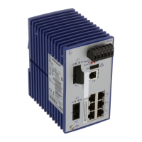
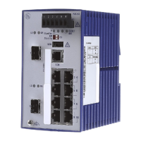
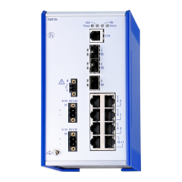
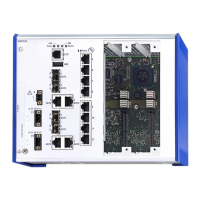
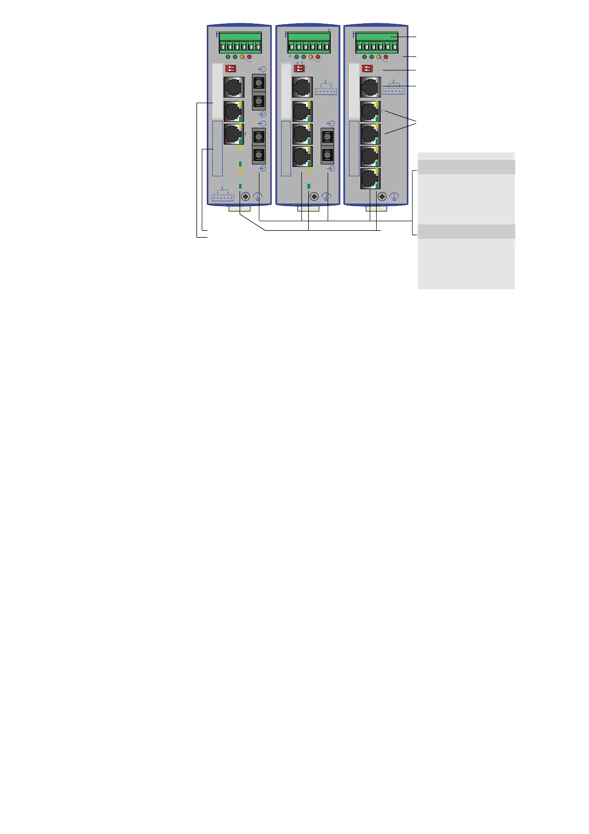
Fig. 1: Overview interfaces, display elements and controls of the RS2-4R
 Loading...